7
SECTION 5: HARDWARE PACK
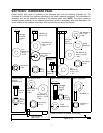
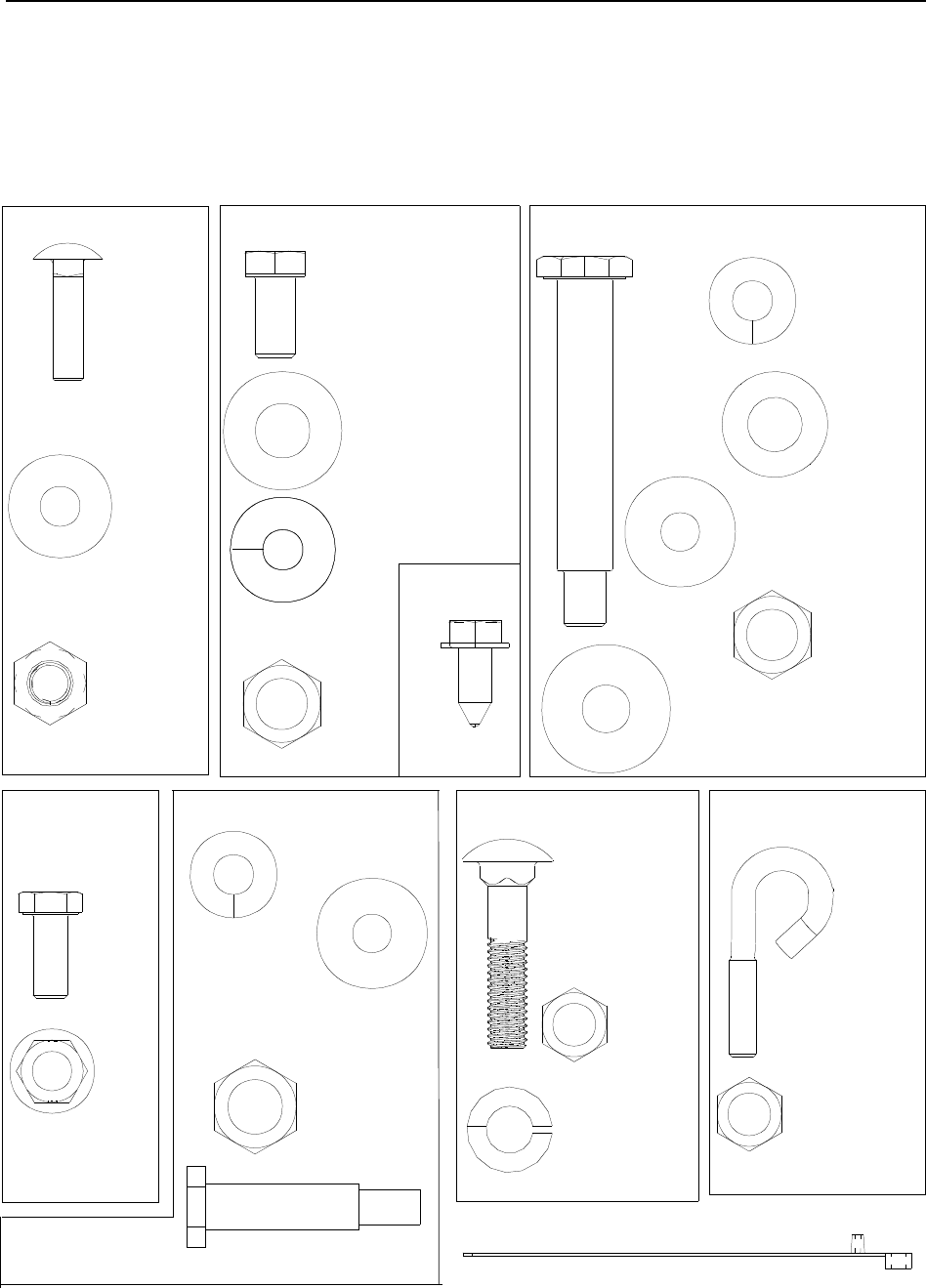
Please identify each piece of hardware in the hardware pack with the following illustrated list. This
illustrated list is divided into sections according to the mower assembly procedure. For convenience in
assembly, sort out the hardware according to the sections given here. NOTE: The actual number of
hardware pieces necessary for an assembly procedure is given in parenthesis after each description. For
actual location of the hardware on the unit, refer to parts list at the end of this manual.
Upper handle to lower handle: Starter rope guide:
Front wheel to deck:
Rear wheel to handle bracket:
Handle bracket to deck: Chute to deck:
Handle bracket
handle & deck:
Cable to handle: (illustrated in half size)
Carriage
Screw (2)
1/4-20 x
1.0
Flat
Washer (2)
.28 ID x
.74 OD
Lock Nut (2)
1/4-20
Hex Bolt (2)
3/8-16 x .75
Flat Washer (2)
.385 x 1.0 OD
x .135
Bell Washer (2)
.401 x .870
x .063
Hex
3/8-16
Self-Tapping
Screw (2)
Nut (2)
Rear Axle
Bolt (2)
.500 x 2.62
Spring
Washer (2)
Bell Washer (2)
.39 ID x 1.13 OD
x .062
Bell Washer (2)
.401 x .870
x .063
Flat
Washer (2)
.510 x 1.373
x .04
Hex Nut (2)
3/8-16
Eye Bolt (1)
Lock Nut (1)
1/4-20
Carriage
5/16-18
Bolt (2)
x 1.5
Hex
Nut (2)
5/16-18
Lock
washer (2)
Hex
5/16-18
Screw (4)
Hex
Flange
Lock
Nut (4)
Front axle bolt (2)
Hex Nut (2)
3/8-16
Bell Washer (2)
.401 x .870
x .063
Bell Washer (2)
.39 ID x 1.13 OD
x .062
.498 x 1.635
Cable tie (1)
through
Handle bracket
to handle:


