13
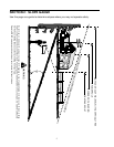
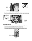
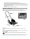
• Insert axle bolt with washers through wheel assembly. See Figure 12 inset.
• Place the small bell washer on the other end of the axle bolt with the crown side towards the wheel.
• Slide the wheel assembly with all the hardware through one of the three holes on the handle bracket. See
Figure 12. Remember to insert the axle bolt and the wheel assembly with hardware through the hole at the
same relative position as the front wheels.
• Secure the axle bolt with a bell washer and hex nut as shown in Figure 12. Attach the other rear wheel in the
same manner.
• Remove blocks and put the mower firmly on level ground.
SECTION 7: CONTROLS
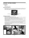
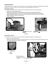
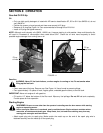
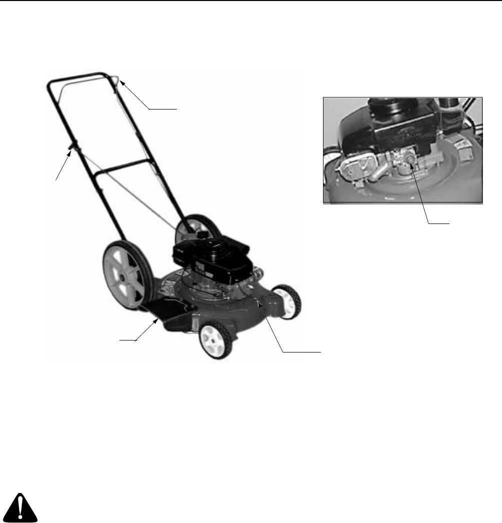
Read this owner’s manual and safety rules before operating your lawn mower. Compare the illustrations in Figure 13
with your lawn mower to familiarize yourself with the location of various controls and adjustments.
Always wear safety glasses while operating the mower, or while performing any adjustments or repairs on it.
FIGURE 13
Recoil Starter
The recoil starter is attached to the handle. Stand behind the unit and pull the recoil starter to start the unit.
Primer
The primer is used to pump gas into the carburetor. Use it to start a cold engine, but do not use it to restart a warm
engine after short shutdown. See Figure 13 inset above for location.
Blade Control Handle
WARNING: This control mechanism is a safety device. Never attempt to bypass its operations.
The blade control handle is located on the upper handle of the mower. The blade control handle must be
depressed in order to operate the unit. Release the blade control handle to stop the engine and the blade.
Blade Control
Handle
Recoil
Starter
Primer
Chute
Deflector
Spark Plug Wire


