


5
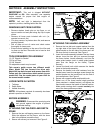
SECTION 2: ASSEMBLY INSTRUCTIONS
IMPORTANT: This unit is shipped WITHOUT
GASOLINE or OIL. After assembly, see separate
engine manual for proper fuel and engine oil
recommendations.
NOTE: Left and right is determined from the
operator’s position, standing behind the tiller.
REMOVING UNIT FROM CARTON
• Remove staples, break glue on top flaps, or cut
tape at carton end and peel along top flap to open
carton.
• Remove all loose parts included with unit (i.e.,
operator’s manual, etc.)
• Cut along corners, lay carton down flat, and remove
packing material.
• Roll or slide unit out of carton and check carton
thoroughly for loose parts.
• Extend control cable(s) to the rear of the tiller and
lay them on the floor. Be careful not to bend or kink
control cable(s).
TOOLS REQUIRED FOR ASSEMBLY
(1)-1/2" Wrench or Socket*
(1)-Pair of Pliers
(1)-3/8" Wrench*
*An adjustable wrench may be used.
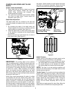
This owner's guide covers two different model
tillers. Model 340 has forward tine drive only.
Model 390 has both forward and reverse tine drive.
Follow only the instructions which pertain to your
model tiller. See the model plate on your tiller for
the correct model number.
LOOSE PARTS IN CARTON
1. Tailpiece
2. Depth Stake
3. Handle Assembly
NOTE: All hardware required for assembly has been
placed in position on the tiller.
BEFORE ASSEMBLY
WARNING: Disconnect the spark plug wire
and ground against the engine to prevent
unintended starting.
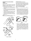
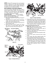
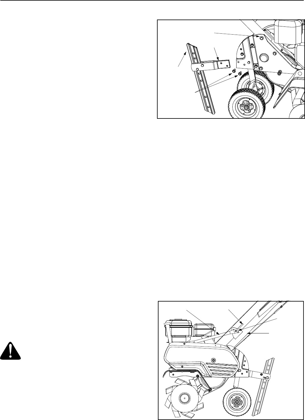
ATTACHING THE TAILPIECE AND DEPTH
STAKE
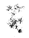
1. Remove the two self-tapping screws on the frame.
Slide the tailpiece into the frame, with the lower
hole in the tailpiece toward the front.
2. Secure with screws just removed. See Figure 2.
Figure 2
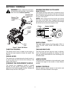
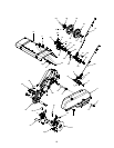
ATTACHING THE HANDLE ASSEMBLY
1. Remove the hex bolt and cupped washer from the
top right side of the frame halves. Hold the cable
guide bracket on the left side of the frame as it will
fall when the bolt is removed. See Figure 3.
2. Insert the handle assembly between the two frame
halves. Insert the hex bolt just removed through
the frame halves, handle assembly, and into the
cable guide bracket (notch in cable guide bracket
goes over the flange on the frame). Tighten
securely.
3. Loosen the hand knob which secures the handle
brace to the handle assembly.
4. Remove the handle knob and hardware from the
handle brace. Insert the carriage screw through the
welded bracket on the handle and into the end of
the handle brace. See Figure 3.
5. Secure with cupped washer and handle knob.
6. Select one of the three handle height positions
(three notches in welded bracket), and tighten the
hand knob to secure the handle in desired position.
Make certain carriage bolt is seated securely into
one of the three positions provided.
Figure 3
Tailpiece
Self-Tapping
Screws
Depth
Stake
Hex Nut and
Cupped Washer
Handle
Crank
Handle
Brace
U-Nut
Handle
Assembly