


Installation
975-0053-01-01 2–15
Connecting DC Wiring
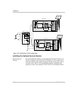
Fuse requirements The combiner board in the Sun Tie XR accepts up to six individual PV
array circuits (positive and negative wires). Each circuit on the combiner
board contains a fuse to protect against over-current. Always replace this
fuse with one of the same type and rating (GBB, 20 amp maximum,
ceramic type, 0.25" x 1.25"). The combiner board is rated for 100 amps
maximum input.
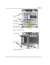
Combiner board
location
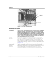
The combiner board PV array input connection block is located in the
lower left-hand section of the Sun Tie XR unit.
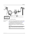
Wiring procedure Before connecting DC wiring, refer to Figure 2-10.
To wire the PV array to Sun Tie XR:
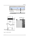
1. Install the DC conduit from the PV arrays to the bottom of the
Sun Tie XR, through one of the knockout holes, as shown in Figure 2-
9. Metal conduit is highly recommended.
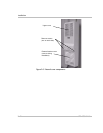
2. Route the wires from the PV array(s) through the conduit and into the
lower section of the Sun Tie XR enclosure, as shown in Figure 2-8.
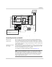
3. Connect the positive (+) wire from the #1 array to the PV PLUS 1
terminal on the combiner board. Check that the wire is in the proper
location and tighten the screw.
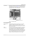
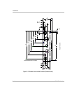
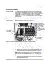
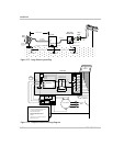
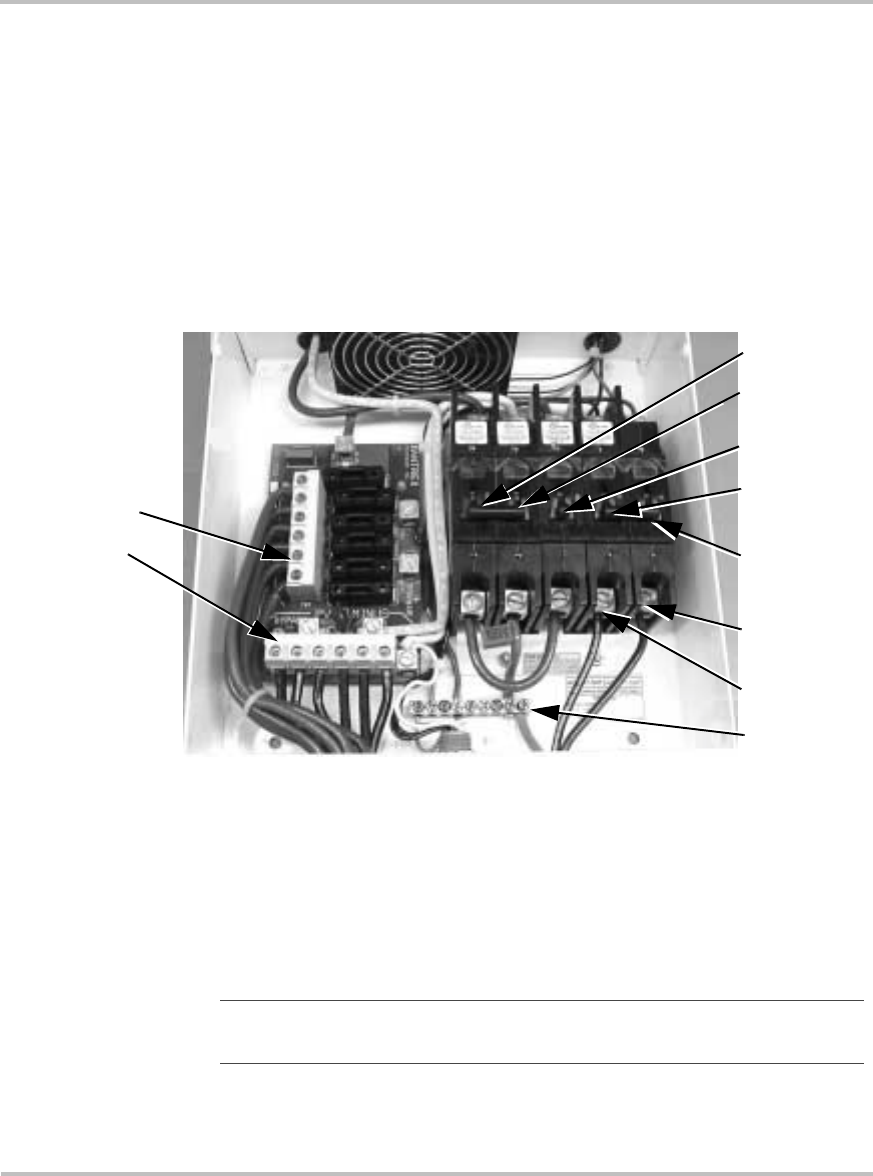
Figure 2-10 Electrical component location and PV array DC connection points
+
–
PVGFP (ganged)
100 amp DC breaker
PVGFP (ganged)
1 amp DC breaker
PV array
100 amp DC breaker
L1 15 amp AC breaker
(ganged)
L2 15 amp AC breaker
(ganged)
L2 breaker AC
connection
L1 breaker AC
connection
Ground bar
PV array wiring to
terminal block
(note polarity)
Note:
If you are using more than one PV sub-array, label the positive
and negative wire pairs appropriately (such as PV 1, PV 2, and so on).