


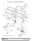
42 Assembly
MAN0506 (Rev. 9/5/2008)
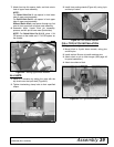
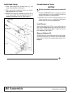
CENTER CUT KIT INSTALLATION
Block Shredded
Never go underneath equipment (lowered to the
ground or raised) unless it is properly blocked and
secured. Never place any part of the body under-
neath equipment or between moveable parts even
when the engine has been turned off. Hydraulic
system leak down, hydraulic system failures,
mechanical failures, or movement of control levers
can cause equipment to drop or rotate unexpect-
edly and cause severe injury or death. Follow Oper-
ator's Manual instructions for working underneath
and blocking requirements or have work done by a
qualified dealer.
To minimize the potential hazards of working under-
neath the cutter, follow these procedures.
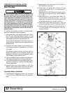
1. Jackstands with a load rating of 2000 lbs or more
are the only approved blocking device for this
cutter. Install a minimum of four jackstands under
the shredder before working underneath unit.
Do not position jackstands under wheels, axles, or
wheel supports. Components can rotate and cause
shredder to fall.
2. Consider the overall stability of the blocked unit.
Just placing jackstands underneath will not ensure
your safety.
The working surface must be level and solid to
support the weight on the jackstands. Make sure
jackstands are stable, both top and bottom. Make
sure shredder is approximately level.
3. With full shredder weight lowered onto jackstands,
test blocking stability before working underneath.
4. If shredder is attached to tractor when blocking, set
the brakes, remove key, and block shredder before
working underneath.
5. Securely block rear tractor wheels, in front and
behind. Tighten tractor lower 3-point arm anti-sway
mechanism to prevent side-to-side movement.
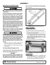
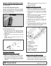
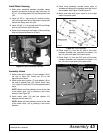
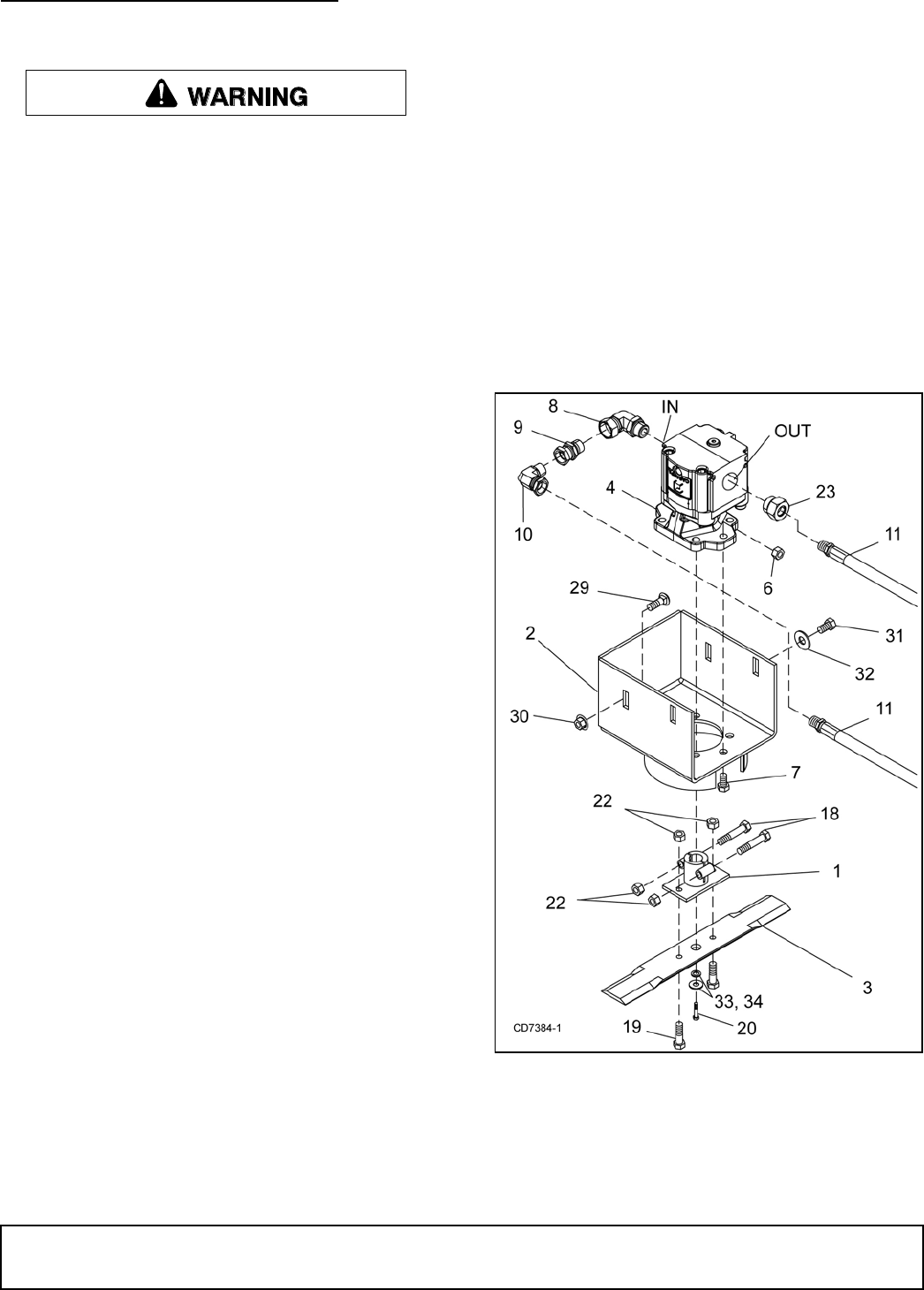
Assemble Motor and Blade
1. Install elbow (8), adapter (9), elbow (10) and hose
(11) to the IN or PRESSURE side of the hydraulic
motor.
2. Install adapter (23) and hose (11) to the OUT or
RETURN side of the motor.
3. Place motor (4) inside motor housing (2) and
secure using six 9/16 NC x 1-1/2 cap screws (7)
lock nuts (6).
Make sure OUT or RETRUN side of motor is on the
open side of the motor housing. Torque hardware
to 171 lbs-ft.
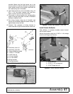
4. Slide blade hub (1) over motor shaft, install 1/4"
key and secure using one 5/16 NF x 1-1/2 cap
screw (20), flat washers (33) and lock washer (34)
in the bottom of the shaft. Torque to 19 lbs-ft.
5. Clamp hub to shaft using two 3/8 NC x 1-3/4 cap
screws (18) and lock nuts (22). Torque to 35 lbs-ft.
6. Secure blade (3) to blade hub using two 3/8 NC x
1-1/4 cap screws (19) and flange lock nuts (22).
Torque to 35 lbs-ft.
Figure 53. Motor Assembly