


Operation 17
MAN0506 (Rev. 9/5/2008)
Keep bystanders away from equipment.
1. Clear the area of all bystanders.
2. Attach the 3-point hitch to the unit but not the PTO
driveline.
3. Raise the unit until the tractor PTO and gearbox
shafts are the same height.
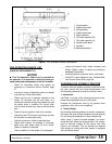
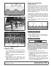
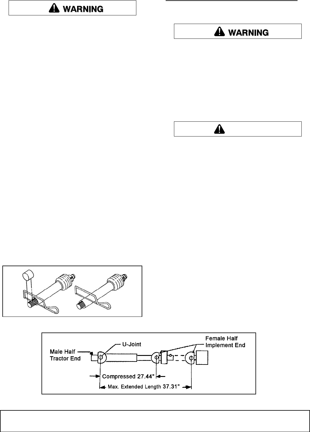
4. Measure the dimension between the shaft grooves
on the tractor and implement ends. If this
dimension is less than 34.81 inches, the shaft will
require shortening.
5. Move the unit to its highest and lowest working
position and measure this dimension again. [The
unit’s shaft can telescope (see Figure 6) before it
has been shortened.]
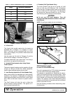
6. If required, shorten the shaft to prevent bottoming
out during use. NOTE: An extra inch of
compression space in the shaft can eliminate
bottoming out during use. Measure to make sure.
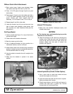
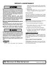
7. Use an abrasive wheel power saw to cut the male
end of the shaft. Cut the same amount from both
the splined shaft and the safety shield. See Figure
5. Use a file to remove any burrs from the cut end.
NOTICE
■ Cut only the male end. Never cut the female end.
8. Never cut more than 9 inches from the male end.
Cutting 1 inch from the male end shortens both the
minimum and maximum lengths by 1 inch.
Figure 5. Cutting the Driveline Shaft
ATTACHING SHREDDER TO TRACTOR
1. Place unit on a level, dry area free of debris and
other foreign object.
Keep bystanders away from equipment.
Connect PTO driveline directly to power unit
PTO shaft. Never use adapter sleeves or adapter
shafts. Adapters can cause driveline failures due to
incorrect spline or incorrect operating length and
can result in personal injury or death.
2. Clear the area of bystanders, especially children.
3. Provide enough clearance to back the tractor
safely into the unit.
■ Do not allow anyone to stand between tractor
and unit when backing up to the unit.
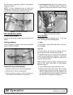
With Quick Hitch Attachment:
4. Set the height of the 3-point hitch so that quick
hitch claws are lower than the mounting pins.
5. Make sure 3-point hitch is set in the non-sway
position. See tractor manual for details.
6. Align the claws under the lower and upper mast
mounting pins while backing up.
NOTE: For a Category II hitch, use the bottom
upper mast hole. For a Category III hitch, use the
top upper mast hole.
7. When the claws are under the pins, slowly raise
the 3-point hitch. Make sure each mounting pin
seats in its respective claw.
8. Release the claw retainer locks to secure the
mounting pins in the claws.
9. Check the top link frame. It should be free to slide
in its mounting slots. This movement allows the
unit to follow the ground contour when cresting a
hill or going through a depression.
Figure 6. Driveline Dimension
CAUTION