


16 Operation
MAN0506 (Rev. 9/5/2008)
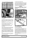
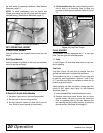
Figure 2. Tractor Front Weight
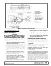
3. 3-Point Hitch
The 3-point hitch models require that the tractor be
equipped with a Category II or Category III 3-point
hitch. If the hitch can be converted from one to the
other, use a Category III to provide a wider stance and
more stability.
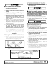
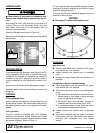
Use the upper top link hole for Category III and the
lower hole for Category II as shown in Figure 3.
For easier attachment, use a quick hitch. If not using a
quick hitch, use optional hitch extension.
4. Hydraulic Requirements when Using Center
Cutter Options
The tractor hydraulic system must be capable of 8 gpm
(30 lpm) at 1500 psi (10,335 kPa). Either closed-cen-
tered or open-centered systems can be used.
5. Load Sensing Hydraulics (3-Point Models Only)
Many newer tractors are equipped with “load sensing”
hydraulics. The operator is responsible for setting the
tractor hydraulic system to provide “float” on the 3-point
hitch. Refer to the tractor manual for specific instruc-
tions.
The “float” feature will allow the unit to follow the
ground contours during operation. This applies to 3-
point mounted machines only.
6. Drawbar (Pull-Type Models Only)
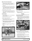
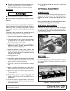
The tractor drawbar must be set to provide 16" (406
mm) on 1-3/8 - 21 or 20" (508 mm) 1-3/4 - 20 between
the end of the PTO shaft and the center of the drawbar
pin for all 1000 rpm PTO. See Figure 4. This dimension
will provide the required clearance for the CV (Con-
stant Velocity) joint on the front of the driveline.
NOTICE
■ Do not use PTO shaft adapters. They will
change the drawbar dimension and can cause driv-
eline failures.
NOTE: On pull-type models, do not cut driveline.
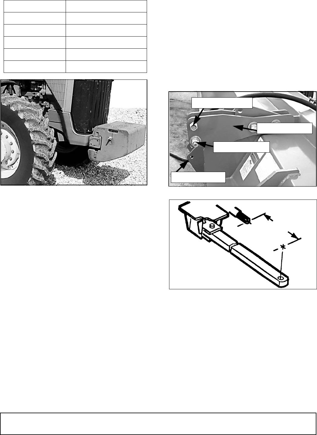
Figure 3. 3-Point Hitch Attachment
Figure 4. Drawbar Dimension
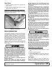
PTO Driveline Length
(3-Point & 2-Point Models Only)
The unit is equipped with a PTO driveline long enough
to fit any tractor and 3-point linkage system.
The operator is responsible for measuring the dimen-
sions of the driveline through its working range. These
dimensions will indicate if the driveline requires short-
ing to operate on the particular tractor/unit attachment
system. The operator must check dimensions before
using the unit for the first time and each time a different
tractor is used with the unit.
Use the following procedure when determining drive-
line dimension:
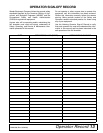
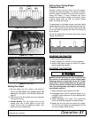
Table 1: Tractor Horsepower (6-8) vs. Unit Width
Width Minimum Horsepower
15′ 90
20′ 120
22′ 132
25′ 150
27′ 162
Top Link Assembly
Upper Top Link Hole
Lower Top Link Pin
Lower 3-Point Pin
1000 RPM
16” or 20”