


Service & Maintenance 31
MAN0506 (Rev. 9/5/2008)
Technical Service for re-balance options or further
details.
Follow the procedure below if rotor removal or replace-
ment is required.
Use a suitable lifting device of sufficient capac-
ity. Use adequate personnel to handle heavy com-
ponents.
1. Clear the area of any bystanders.
2. Shut off tractor, place all controls in neutral, set
parking brake, remove key, and wait for all moving
parts to stop.
3. Remove PTO driveline from the shredder.
4. Fully disconnect the shredder from the tractor.
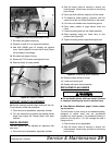
5. Remove wheel arms (casters or struts).
6. Use a hoist, crane, or frame of sufficient capacity to
raise the front of the unit and allow the back of the
unit to rest on a solid surface (blocks).
7. Leave lifting device attached while working on
rotors to prevent tipping.
Removing Components
Refer to Replacing Flails, page 29, for knife or knife
component replacement.
Refer to Servicing Rotors, page 30, before proceeding
with these steps.
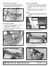
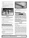
1. Follow steps in the previous section to prepare and
position shredder. Support each end of the rotor
(flail tube) to be removed with a crane or hoist.
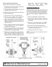
2. Remove bearing locking collar (see Figure 36).
3. Remove the six bolts holding the bearing plate to
the body assembly.
4. Slide rotor out to disengage from the center drive
coupling.
5. Thoroughly clean and inspect gearbox drive
couplings for wear and replace if any wear is
detected. Also inspect the rubber O-ring for wear or
tears and replace if any wear or tears are detected.
6. Remove crossmember from the underside of the
shredder, providing access for the removal of the
gearbox.
7. Remove gearbox, if damaged. This will require
removal of the second rotor (repeat steps 1-5
above).
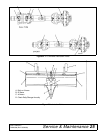
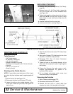
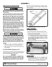
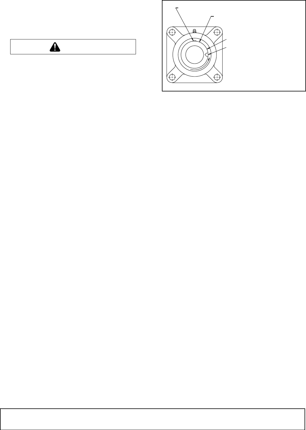
Figure 36. Locking Collar
Replacing Components
1. Place new stud bolts into gearbox using Loctite
®
No. 271 or equivalent.
2. Remount gearbox. The gearbox oil dipstick should
protrude out the top panel of the shredder for
checking and servicing. Reinstall the nuts and lock
washers securing the top of the gearbox to the
shredder gearbox mount plate and torque to
specifications in Bolt Torque Chart, page 63.
3. Remount the crossmember securing the bottom of
the gearbox and torque to specifications in Bolt
Torque Chart, page 63.
4. Install drive couplings and reapply new grease
around entire O-ring and gear teeth surfaces.
5. Install rotors (flail tubes) in the opposite fashion as
removal. Position rotors with each end supported
by a crane or hoist so that it is aligned with the gear
coupling and gearbox output shaft center lines.
The bearing (stub shaft) end of the rotor will
protrude out of the hole in the end sheet.
6. With gentle care not to damage gear coupler teeth
or O-ring, provide pressure to align gear teeth and
slide the rotor back into its original position.
NOTE: When re-installing rotors, the gear coupling
grease fitting will need to be temporarily removed
to allow for air to purge from the coupler assembly
during installation. After successful installation,
reinstall grease fitting and re-service.
7. Reinstall bearing plate assembly and bolts, and
apply appropriate torque.
8. Reinstall bearing locking collar and tighten (see
Figure 36).
NOTICE
■ If removing rotor drive coupling, use Loctite No.
271 or equivalent and special high collar lock
washers to keep bolts from loosening.
CAUTION
MAN0506003
P E E R
F S 2 1 1
LOCKING COLLAR
LOCKING COLLAR SET SCREW
SHAFT
FOR REMOVAL: TAP
WITH A HAMMER AND
PUNCH AFTER LOOSENING
SET SCREW.
FOR INSTALLATION:
REVERSE PROCEDURE