


26 Assembly
MAN0253 (Rev. 3/10/2007)
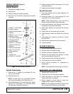
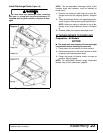
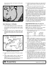
leave the seat safety circuit open and the power
unit will not run.
Figure 25. F Series Seat Connection
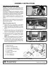
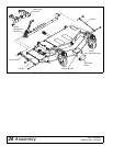
Deck Attachment - All Models
1. Use the height adjustment handle (or height adjust-
ment switch on PowerTilt models) to raise or lower
rear pivot lift arm and align arm with mounting
brackets.
2. Attach rear pivot lift arm in desired power unit
mounting bracket holes and connect with spring
loaded pins. See Figure 26 for correct hole loca-
tions.
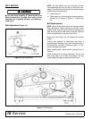
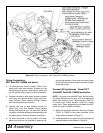
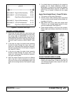
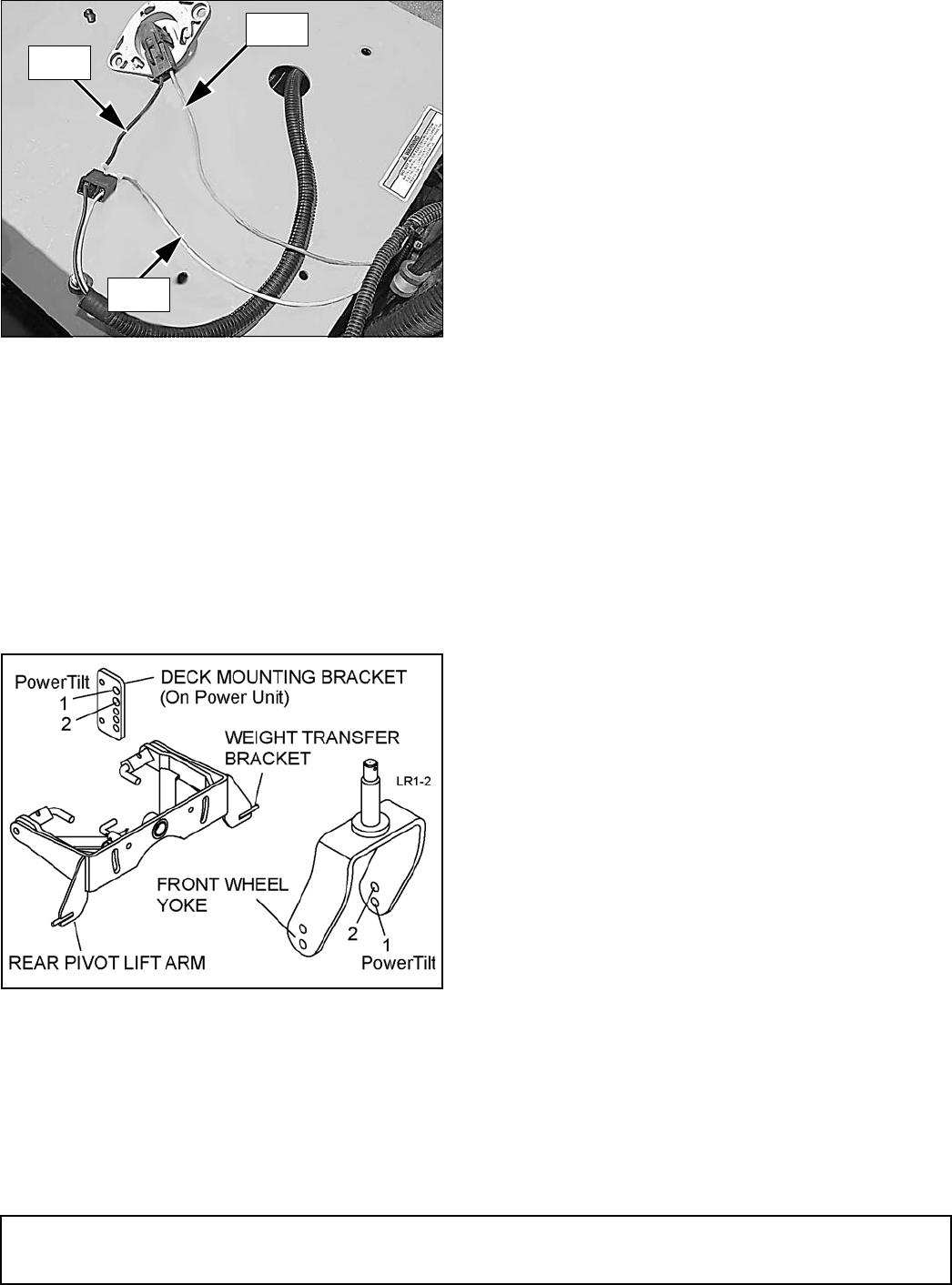
Figure 26. Mounting Hole Location
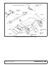
3. Attach driveline from deck to PTO shaft on power
unit.
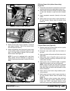
4. Attach weight transfer chains to right and left
weight transfer brackets on rear pivot lift arm.
NOTE: Stepping on the weight transfer arms with
your foot will make attaching chains easier.
5. Install flat washers and safety pins in right and left
weight transfer brackets to secure chains into posi-
tion.
6. Close power unit hydraulic pump dump valves.
7. After deck is attached to power unit, raise deck and
rotate parking stand into the storage position.
NOTE: Attach rear pivot lift arm in hole position 1 on
deck mounting brackets when front wheels are in hole
1 on front wheel yoke. This will put the deck in the high
cut range, (2 to 5 inches - manual, 1-1/4 to 5-1/2 inches
- PowerTilt™). Attach weight transfer chains to weight
transfer brackets using four links. Use the PowerTilt™
in hole position 1 as shown in Figure 26.
NOTE: Attach rear pivot lift arm in hole position 2 on
deck mounting brackets when front wheels are in hole
2 on front wheel yoke. This will put the deck in the low
cut range, (1 to 4 inches). Attach weight transfer chains
to weight transfer brackets using five links.
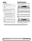
Adjust Mower Deck (Figure 27 & Figure 29)
NOTE: Adjust side-discharge decks 3/8” higher in the
rear than the front using these instructions.
NOTE: Make sure adjustment rods are set to dimen-
sions given in Figure 27 prior to adjusting deck.
1. Make sure power unit tire pressure is set equally
on both sides of power unit.
Standard Front: 12 psi Drive Tire
Rear: 18 psi Rear Caster
Front: 45 psi Deck Caster
2. Place deck in the lowest and highest cutting posi-
tions.
NOTE: If MX54/MX61 lift handle lever will not lock
into position, adjust ground rod by loosening jam
nut and turning rod using the flat provided until
positions are functional. Tighten jam nut.
3. Place a straightedge on the mower deck, front to
rear, and measure from bottom of straightedge to
ground. On side discharge mowers, rear measure-
ment should be 3/8" higher than front. On decks
with mulching kits, 3/8" to level is acceptable.
4. If the measurement is not 3/8" greater at the rear,
check to make sure mower attachment arms are in
the correct mounting bracket holes on the power
unit, (see Figure 26).
5. Adjust the mower to 3/8" higher in the rear by
adjusting the right and left lift rods. Adjust lift rods
by loosening jam nuts and turning rods using the
flat provided in the center of the rods. Lengthening
the rods lowers the front edge of the deck.
Shortening the rods raises the front edge of the
deck. Tighten jam nuts when deck is 3/8" higher in
the rear.
Black
Green
DP5T2
Purple
(Rev. 1/7/2010)