


Assembly 11
29936 (Rev. 5/18/2007)
and idler bracket. Install 5/8 x 2-1/2 carriage bolt
through slot and idler, and secure with 5/8" nut and lock
washer.
Install a 5/8 x 3" bolt through second idler. Put these
5/8" flat washers over bolt, and install assembly to right
side of rear vertical slot in idler bracket. Secure with a
5/8" flat washer and nut.
After drive belt has been installed, install rear belt
shield (19) over bolt installed in rear idler and secure
with another 5/8" nut and two 5/8" flat washers.
Drive Sheave
Remove paint from bore of drive sheave. Install large
drive sheave onto tractor belt pulley shaft using tractor
key and nut. A flat washer is provided to be installed
between nut and sheave. If your tractor has a tapered
shaft which is too small for this sheave (made prior to
1939), it will be necessary to install a late model belt
pulley shaft (AC part 208959) or to build up the old
shaft with shims or weld to fit.
Belt Assembly and Adjustment
Slide mower under tractor and pin push channel to idler
bracket with 5/8 x 1-3/4 clevis pin. Put belt on, see Belt
Assembly and Adjustment. Make major adjustments by
sliding mower fore and aft using 6 holes in channel arm
as required. Make minor adjustments with idlers.
Lift Assembly
Attach the lift frame (11) to tractor using upper right
hand clutch housing hole for front end of the bracket
and 1/2" vertical hole in square tubing on tractor foot
rest for the rear attaching point.
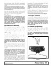
For hydraulic lift, assemble triangular plate (12) onto lift
frame using 5/8 x 2-1/4 bolt (39), bushing (13), two flat
washers, and lock nut with forked end rearward and
down.
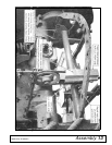
Remove cylinder from rear of tractor, remove hose and
install longer hose provided, using 45° swivel adaptor
between valve and hose. Install 90° swivel end of hose
in cylinder and straight end in 45° adaptor previously
installed.
Install cylinder onto attaching frame on inside of frame
at the threaded hole using a 5/8 x 3" bolt. Put bolt
through cylinder, then run a nut up on the bolt, screw
bolt through the plate, install a nut on outside and
tighten. Use a 7/16" clevis pin and cotter pin to attach
the cylinder to the triangular plate.
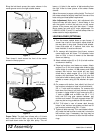
Attach 33-link chain (17) to keyhole lug on mower deck
and secure with plastic caplug (14). Attach 7-link chain
(15) to triangular plate with 3/8 x 1-1/4" bolt and flange
lock nut. Connect the chains together by installing the
lower end of 7-link chain (15) through the middle of
longer chain (17), and secure by installing 3/16" safety
pin (16) through end of link in chain (15).
Adjust chains so the mower raises level without pulling
sideways or hitting rear tires. Also adjust chain so
mower does not hit bottom of tractor or tires when fully
raised.
Check to make sure the lift triangle does not hit the
tractor starter. If it does, use washers to shim lift trian-
gle or lift support frame away from tractor.
If manual height adjustment is used, refer to page 22.
Tractor Wheel Adjustment
On model “B” tractors, the right tire may be fully
extended and the mower will cut beyond it, but the left
rear tire must be moved in if the mower is to cut clear.
For model “C” tractors, the right tire must be put within
four inches of its most inward position for the mower to
cut beyond the tire track. With the left tire in its most
inward position, the mower will still not quite cut
beyond the tire track.
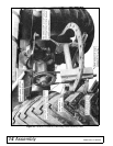
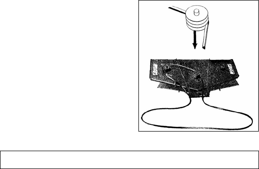
Belt Assembly and Adjustment
Models used on: 59C, L59, and L306 model AC52,
AC54, BMC, B-25, D, D10-D12, F, F10, H3, GM2,
GM4, JD85, JD95, JM, K17, K22, K28, KD, KL, K210,
K260, MF, M25, S, S55, VC, U, etc.
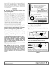
First put belt on the bottom groove, right hand side of
the center sheave. Then thread it to left, around the left
hand sheave.
Figure 6.