


Assembly 23
15148 (Rev. 2/9/2007)
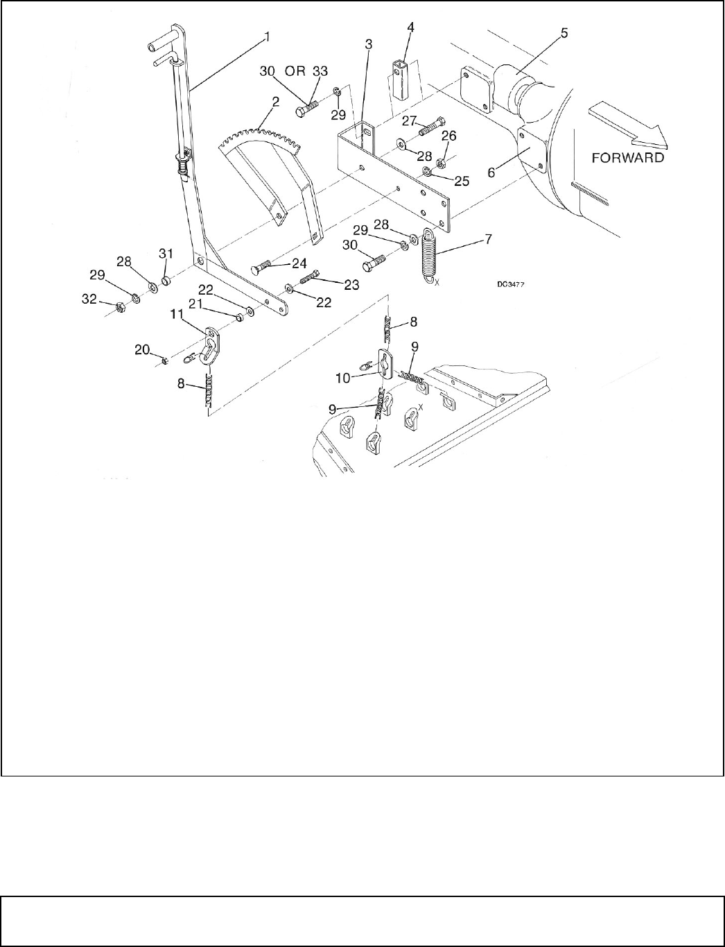
Then install sleeve (31), washer (28), lock washer (29),
and nut (32). Tighten all hardware.
NOTE: Install left lever (1) between steering wheel rod
and gas tank.
Place washer (22) on bolt (23) and insert through sec-
ond hole from front of left lever (1). Then install washer
(22), sleeve (21), lift lug (11), and nut (20) on bolt and
tighten.
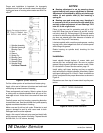
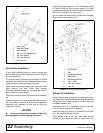
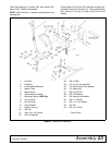
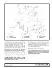
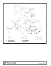
Figure 17. Manual Lift Installation
1. Lift Lever
2. Lift Sector
3. Lift Attachment Bracket
4. Spacer Tube
5. Starter Motor*
6. Transmission Housing*
7. Extension Spring, L306 Only
8. 13 Link Chain
9. 33 Link Chain
10. Chain Bracket
11. Keyhole Lift Lug
20. 3/8" Nut
21. 3/8 x 1/2 x 1/4" Sleeve
22. 3/8" Flat Washer
23. 3/8 x 2" Bolt
24. 1/2 x 1-3/4" Carriage Bolt
25. 1/2" Extra-Heavy Lock Washer
26. 1/2" Heavy Nut
27. 5/8 x 2-3/4" Bolt
28. 5/8" Flat Washer
29. 5/8" Heavy Lock Washer
30. 5/8 x 1-1/4" Bolt
31. 5/8 x 1 x 7/16" Sleeve
32. 5/8" Nut
33. 5/8 x 2-1/4" Bolt
* Tractor Parts