


Dealer Service 15
15148 (Rev. 2/9/2007)
DEALER SERVICE
The information in this section is written for dealer ser-
vice personnel. The repair described herein requires
special skills and tools. If your shop is not properly
equipped or your mechanics are not properly trained in
this type of repair, you may be time and money ahead
to replace complete assemblies.
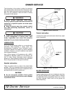
■ Before working underneath, block mower
securely. Hydraulic system leak down and failure of
mechanical or hydraulic system can cause equip-
ment to drop.
■ Keep all persons away from operator control
area while performing adjustments, service or
maintenance.
■ Always wear relatively tight and belted clothing
to avoid entanglement in moving parts. Wear
sturdy, rough-soled work shoes and protective
equipment for eyes, hands, hearing and head.
BLADE SPINDLE REPAIR
Removal
Remove blade from spindle. Remove belt shield.
Remove belt from pulleys.
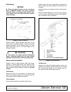
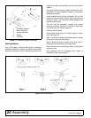
Disassemble split taper bushing (located on top of pul-
ley) by removing the two bolts and inserting them into
the threaded holes in bushing flange. Tighten bolts
alternately to remove split taper bushing. Remove key
and pulley.
Remove four bolts attaching spindle to mower frame
and remove spindle.
Repair Tips
As a reference point, the grease fitting is in the top por-
tion of spindle housing.
To minimize wear, bearing cups, cones and sleeves are
press fit to shaft and will require a press of similar
device for removal.
When disassembling, support housing casting to pre-
vent damage. Remove bearing cups by placing a
punch in housing slots and driving out. Alternate punch
positions from side to side. Use care to prevent hous-
ing damage.
Permatex 3D Aviation Form-A-Gasket
®
or equivalent is
recommended as a sealant for spindle repair.
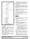
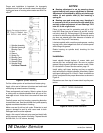
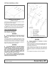
Disassembly
Drive spring pin (5) out of spindle shaft (9). Support
spindle in a press and push shaft (9) down through
housing (2). Remove seals from housings. Remove
bearing cups from housings. Remove bearing cone
from spindle shaft.
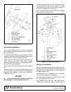
Assembly
Bearing cups and cones are designed to work together.
It is important to position them so bearing cone taper
mates with bearing cup taper.
Lubricate new cups (7) with a light oil. Place them in
spindle housing (2) so they will mate with cones (6).
Seat cups (7) against machined shoulder of housing
with a press or by placing a large soft drift on the flat lip
and driving them into housing.
Place bottom bearing cone (6) onto spindle shaft (9)
with taper up. Seat on bottom shoulder of shaft with a
press.
Insert shaft and bearing cone assembly through bottom
of housing (2). Fill housing cavity with a lithium grease
of #2 consistency with a MOLY (molybdenum disulfide)
additive.
Place top cone (6) on shaft (9), taper down.
Apply a thin coat of Permatex
®
to shaft area where
sleeve (4) will seat.
Insert sleeve (4) on shaft (9) and press sleeve and
bearing onto shaft until all bearing free play is removed
and there is a slight drag (similar to adjusting the front
wheel bearings on an automobile). Check by spinning
spindle. It should turn freely.
Be careful not to overtighten bearings. Proper bearing
adjustment is essential to good bearing life.
Should you overtighten bearings, hold spindle housing
and rap spindle shaft with a lead hammer to loosen
bearings. Readjust bearings until proper setting is
obtained.
NOTICE
■ Improper positioning of seals can cause seal
failure.
A WARNING
A CAUTION