


Operation 11
MAN0875 (2/8/2011)
OPERATION
The operator is responsible for the safe operation of
this Mow’n Machine. The operator must be properly
trained. Operators should be familiar with the power
unit, all attachments that will be used, and all safety
practices before starting operation. Read the safety
rules and safety decals on page 5 through page 10.
Operators must be instructed in and be capable
of the safe operation of the equipment, its attach-
ments, and all controls. Do not allow anyone to
operate this equipment without proper instructions.
Do not operate power unit with attachment
removed. Attachment is required for power unit
stability.
Never direct discharge toward people, animals,
or property.
Moving steering levers rapidly from forward to
reverse or reverse to forward could cause loss of
control.
Start engine from operator's seat after disen-
gaging power unit PTO and placing steering levers
in neutral.
Stop power unit and equipment immediately
upon striking an obstruction. Turn off engine,
remove key, inspect, and repair any damage before
resuming operation.
CONTROLS AND SWITCHES
Know your controls and how to stop engine and
attachment quickly in an emergency.
The Control and Indicator console is located on the
right fuel tank for FZ23B and FZ28K models. This con-
sole contains controls needed to operate this unit. PTO
switch (2) is used to engage attachments: pull up to
engage, push down to disengage.
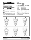
Deck Height/Power Tilt™
Adjustment Switch
The deck height and Power Tilt™ switch is used with
MXT or MX decks equipped with the Power Tilt™ Kit.
Push the toggle switch forward to raise the deck and
pull back to lower the deck to the desired cutting
height. For Power Tilt operation, pull back and hold the
toggle switch to lower the deck and cycle through to the
tilt position. Release switch when deck reaches maxi-
mum tilt position. To lower the deck, push and hold tog-
gle switch until it cycles to the desired cutting height.
NOTE: Power Tilt™ feature must not be used when sit-
ting in the seat.
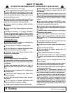
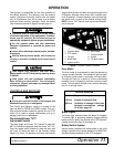
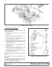
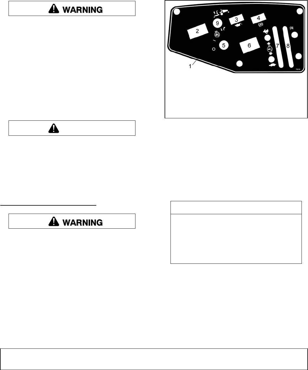
Figure 1. Console Control Locations
Hour Meter
The hour meter is programmed to alert the operator at
various service intervals. The change oil light will flash
at 20 hours (initial break in) and every 100 hours after.
The light will flash for a period of 4 hours (alternating
between hours & change oil) and then resume normal
mode. The hour glass will flash every second indicating
that it’s in running mode.
Brake Lights
The brake light indicates when the brake is engaged.
To ensure light is operating properly, engage parking
brake and turn ignition key switch to the “ON” position.
Control panel brake light (4) should be on.
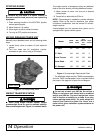
Safety Switch System
Several safety switches are incorporated in the unit’s
design to prevent it from being started out of NEUTRAL
(handles pivoted outward) or with PTO engaged.
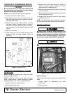
CAUTION
Service Intervals
20 hrs Engine oil change (break in)
100 hrs Engine oil change & filter
500 hrs Hydraulic oil change & filter (see
hydraulic transmission - change
oil & filter, page 18.)
1. Console decal
2. PTO switch
3. Oil light
4. Brake light
5. Ignition switch
6. Hour meter
7. Throttle control
8. Choke
9. Tilt deck switch