


10 Assembly
29931 (Rev. 8/10/2007)
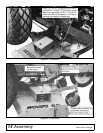
ASSEMBLY
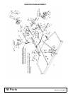
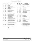
MOWER FRAME ASSEMBLY
Open box and lay parts out in an orderly manner.
Side Shield (See page 20)
Attach side shields (2 and 3) to mower with 3/8 x 1"
bolts and flange nuts. A side discharge chute (5) may
be installed on discharge end of mower in place of that
side shield.
Center Shield (See page 20)
To allow more lift on tractors with minimum ground
clearance, such as Fords, IH LoBoy, Kubotas, Satohs,
etc., a center belt shield is not offered. If the box of
parts has a center belt shield, bolt center belt shield
bracket (34) to deck with 3/8 x 1" bolt. Bolt center
shield (10) to bolts welded in deck and bracket (34).
Side Skids
Bolt skids using 3/8 x 1" heat-treated bolts (torque to 35
lbs-ft), lock washer, and nuts in such a position that
they will be carried close to the ground, but so they do
not ride continually on the ground when mower is
operated at desired mowing height.
Front Toe Guards (See page 20)
Front toe guards (6) are furnished for some mowers.
When provided, bolt them to the front of the mower,
using 3/8 NC x 3/4" carriage bolt and 3/8" flange lock
nuts. (NOTE: On 59 & L59 where casters are installed
on outer deck rails, bolt toe guards to mower so outer
ends are about 2" in from end of deck. Otherwise, end
of toe guard will be about 1/2" in from end of deck.)
Crosswise Rear Support (See page 20)
Install bushing (16) into center hole in crosswise rear
support and bolt it to back of mower deck with short bar
forward and offset up using 1/2 x 2" hex head cap
screw and 1/2" flange lock nut.
NOTE: On L59, L306F10-2, “S”, JD85, JD95 & GM4
mountings, a special crosswise rear support is pro-
vided. If tractor is equipped with turf tires, use upper
center hole in crosswise support, and for Ag tires, use
lower hole.
Channel Arms (See page 20)
Slide mower under tractor. Attach channel arms (12) to
mower frame using 5/8 x 1-1/2" clevis pin and safety
pins. Pin crosswise rear support bar (15) between
channel arms and bolt center to frame angle bracket as
shown in the main assembly drawing.
Casters
If casters are used, see page 19, except for the L59
mower on Ford 1000, 1600, 1700, 1900, and Satoh
S650. (See mounting frame drawing in manual.)
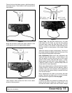
Front Roller
Put front roller bracket (28) on left side and front roller
bracket (27) on right side of mower using 3/8" carriage
bolts and nuts. This will put the highest hole in brackets
rearward.
Assemble roller and roller rod (26) in rear holes in
brackets (27 & 28). Secure with 3/16" cotter pins. Turn
roller by hand to see that it turns freely.
MOUNTING FRAME ASSEMBLY
(SEE PAGE 16)
Idler & Mounting Bracket Assembly
Remove drawbar from tractor and bolt idler bracket (4)
between wheel housings, using holes where drawbar
was attached. Secure with 5/8 x 1-1/4 bolts and lock
washers.
NOTE: If tractor is equipped with 13.6 - 16 turf tires, the
wheel spacer kit (16) (optional) must be used. Use one
spacer between each wheel and axle flange.
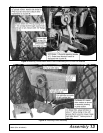
NOTE: If tractor is equipped with 3-point lift, remove
outer bars holding lower arm in place and bolt idler
bracket to tractor. See Figure 9 for further instructions.
Idler Assembly to Idler Bracket
Install one V-groove idler (8) on the outside of left verti-
cal slot of idler bracket (4) and one to inside of right
vertical slot. Use three 5/8" flat washers between idlers
and idler bracket. Bolt together using 5/8 x 2-1/2 car-
riage bolts, lock washers, and nuts.
Drive Pulley
Remove PTO shield on back of tractor. Install bushing
(12) into 6-1/2" pulley (11) and install assembly onto
PTO shaft. Adjust drive sheave (11) fore and aft for
proper alignment after belt is installed. Torque bolts to
12 lbs-ft alternating back and forth on each bolt at least
six times.
Belt Assembly and Adjustment
Slide mower under tractor.
NOTE: It may be necessary to remove one of the chan-
nel arms attached to mower deck.
After mower is centered under tractor, reinstall push
channel and pin push channels to idler and mounting
frame using 5/8 x 1-3/4 clevis pin.