


Assembly 11
29931 (Rev. 6/29/2007)
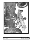
Slide mower under tractor and pin the push arms to the
inside of the mounting brackets using 5/8 x 1-3/4 clevis
pin (66) and safety pin (48).
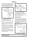
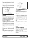
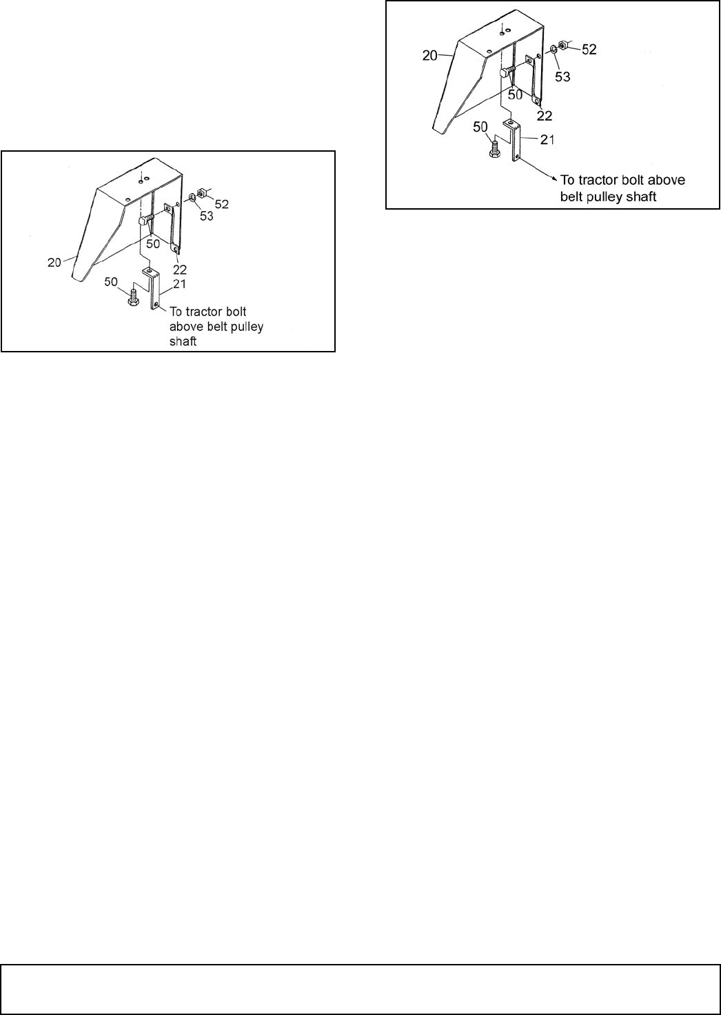
Shield Attaching Bracket
Remove belt pulley and install shield bracket (21) to
upper bolt on end seal cap of belt pulley housing, with
short flange pointing outward.
Figure 9. Shield Attaching Bracket
Drive Sheave
Remove paint from bore of large drive sheave and
attach it to the tractor belt pulley shaft using splined
bushing (19) provided, with flange on the outside. Posi-
tion so the face of the bushing is about flush with the
end of the shaft and torque bushing bolts evenly to 12
lbs-ft alternating back and forth at least six times.
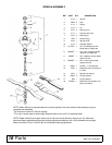
Belt Assembly & Adjustment
Put the belt on the drive according to the pictures and
instructions on page 12.
NOTE: Make major adjustments by sliding the mower
fore and aft using the five holes in the end of the chan-
nel arms as required. Make minor adjustments with
idlers but keep them slightly above being in line with
the groove in which the belt runs on the mower center
sheave.
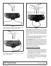
Upper Belt Shield
Bolt the angle bracket (22) to the back of the PTO
shield support bracket using the existing right hand
bolt. Install so the bracket angles rearward and out-
ward.
Attach the shield (20) to the two attaching angles (21 &
22) using 3/8 NC x 3/4 hex head cap screw (50) and
secure with lock washer (53) and hex nut (52).
Figure 10. Upper Belt Shield
Lower Belt Shield
Install lower belt shield (26) over bolt holding rear V-
idler to idler bracket. Secure with a 5/8" flat washer on
each side and a 5/8" nut. See page 16.
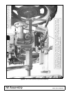
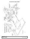
Lift Assembly
Attach lift arm (6) to rockshaft on right side of tractor
with large hole to rear. Attach lower lift bar (5) to lift arm
(6) using 5/8 x 1" bolt, flat washer and spacer bushing
(7). Attach lift chains to keyholes in mower lift lugs and
secure with plastic caplug (4). Hook eye bolt through
top of chain and into cross plate of lift bar.
Raise the mower on the tractor hydraulic system
slightly and adjust eye bolts to carry mower level.
Adjust so mower does not hit tractor or tires when fully
raised.
NOTE: On “240” with rear rockshaft, it is necessary to
use manual lift. See page 24.
Casters
If casters are used see page 19 and page 20.
Manual Lift Assembly
See page 24 for manual lift assembly installation
instructions.
Belt Assembly and Adjustment
Models used on: 59C, L59, and L306 model AC52,
AC54, BMC, B-25, D, D10-D12, F, F10, H3, GM2,
GM4, JD85, JD95, JM, K17, K22, K28, KD, KL, K210,
K260, MF, M25, S, S55, VC, U, etc.
First put belt on the bottom groove, right hand side of
the center sheave. Then thread it to left, around the left
hand sheave.
LA7
LA11