


7
MAINTENANCE AND REPAIR INSTRUCTIONS
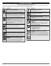
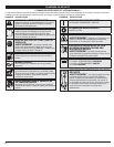
MAINTENANCE SCHEDULE
Perform these required maintenance procedures at the frequency stated in the table. These procedures
should also be a part of any seasonal tune-up.
NOTE: Some maintenance procedures may require special tools or skills. If you are unsure about these
procedures take your unit to any non-road engine repair establishment, individual or authorized
service dealer.
NOTE: Maintenance, replacement, or repair of the emission control devices and system may be
performed by any non-road engine repair establishment, individual or authorized service dealer.
In order to assure peak performance of your engine, inspection of the engine exhaust port may be
necessary after 50 hours of operation. If you notice lost RPM, poor performance or general lack of
acceleration, this service may be required. If you feel your engine is in need of this inspection, refer service
to any non-road engine repair establishment, individual or authorized service dealer for repair. DO NOT
attempt to perform this process yourself as engine damage may result from contaminants involved in the
cleaning process for the port.
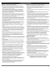
WARNING:
To prevent serious injury, never perform maintenance or repairs with unit
running. Always service and repair a cool unit. Disconnect the spark plug wire to ensure
that the unit cannot start.
FREQUENCY MAINTENANCE REQUIRED SEE
Before starting Fill fuel tank with fresh fuel p. 6
Every 10 hours Clean and re-oil air filter p. 8
Every 25 hours
Check and clean spark arrestor
Check spark plug condition and gap
p. 8
p. 8
Every 50 hours Inspect exhaust port and spark arrestor screen for clogging or
obstruction to assure maximum performance levels
p. 8
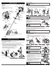
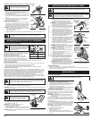
USING THE CUTTING BLADE
Before operating the unit with the cutting blade, stand in the
operating position (Fig. 23). Refer to Holding the Trimmer.
Cutting Blade Operating Tips
To establish a rhythmic cutting procedure:
• Plant feet firmly, comfortably apart.
• Bring the engine to full throttle before entering the material to
be cut. At full throttle the blade has maximum cutting power
and is less likely to bind, stall or cause blade thrust (which can
result in serious personal injury to the operator or others).
• Cut while swinging the upper part of your body from left to right
(Fig. 24).
• Always release the throttle trigger and allow the engine to return to idle speed when not cutting.
• When you are finished, always unsnap the unit from the harness before taking off the harness.
• Swing the unit in the opposite direction as the blade spins, which increases the cutting action.
• After the return swing, move forward to the next area to be cut plant your feet again.
• The cutting blade is designed with a second cutting edge. You can use it by removing the blade,
turning it upside down, and reinstalling it.
To reduce the chance of material wrapping around the blade, follow these steps:
• Cut at full throttle
• Swing the unit into material to be cut from your left to your right (Fig. 24)
• Avoid the material just cut as you make the return swing
Fig. 24
Fig. 23
WARNING:
Always wear eye, hearing, foot,
body protection and the shoulder strap to reduce
the risk of injury when operating this unit.
WARNING:
Do not use the cutting blade for
edging or as an edger. Severe personal injury to
yourself or others can result.
WARNING:
Blade thrust may occur when the
spinning blade contacts an object that it does
not immediately cut. Blade thrust can be violent
enough to cause the unit and/or operator to be
propelled in any direction, and possibly lose
control of the unit. Blade thrust can occur
without warning if the blade snags, stalls or
binds. This is more likely to occur in areas where
it is difficult to see the material being cut.
WARNING:
The blade continues to spin after the engine is turned off. The coasting
blade can seriously cut you if accidentally touched.
WARNING:
Do not clear away any cut material with the engine running or blade
turning. To avoid serious personal injury, turn off the engine. Allow the blade to stop
before removing materials wrapped around the blade shaft.
WARNING:
Do not sharpen the cutting blade. Sharpening the blade can cause the
blade tip to break off while in use. This can result in severe personal injury to yourself or
others. Replace the blade.
LINE INSTALLATION
This section covers both SplitLine™ and standard single line installation.
Always use original equipment manufacturer 0.105 in. (2.67 mm) replacement line. Other types of line may
make the engine overheat or fail.
There are two methods to replace the trimming line:
• Wind the inner reel with new line
• Install a prewound inner reel
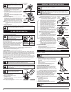
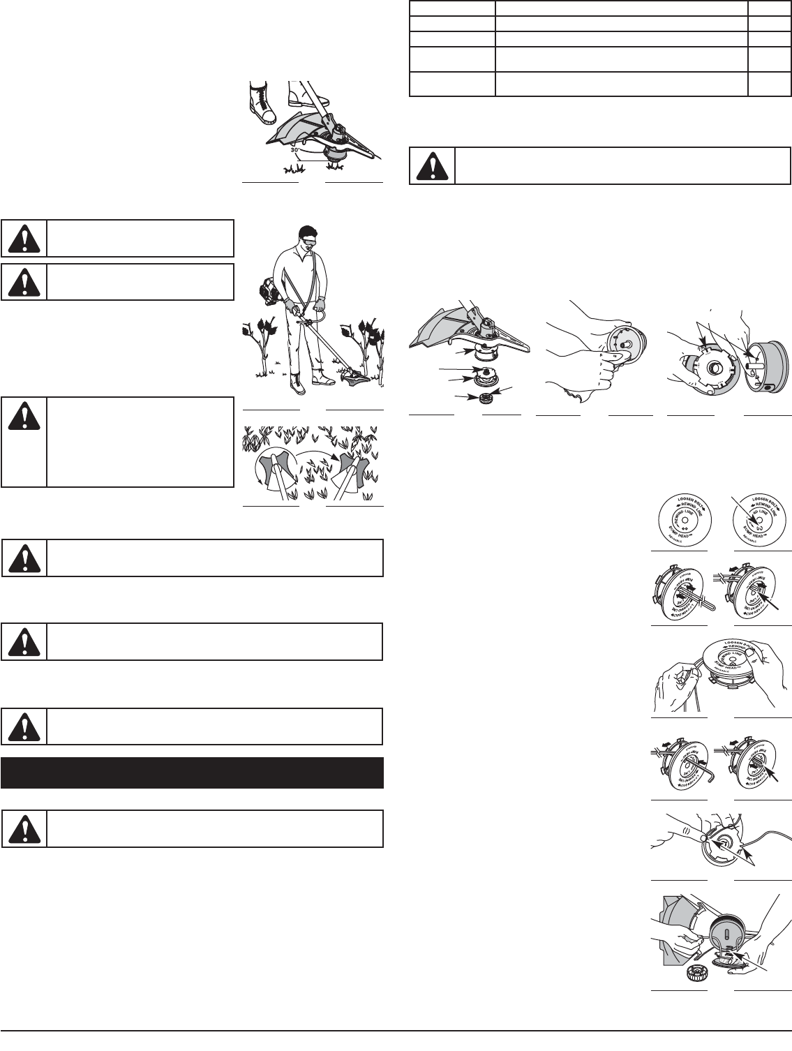
Winding the Existing Inner Reel
1. Hold the outer spool with one hand and unscrew the Bump Knob clockwise (Fig. 25). Inspect the bolt
inside the bump knob to make sure it moves freely. Replace the bump knob if damaged.
2. Remove the inner reel from the outer spool (Fig. 25).
3. Remove spring from the inner reel (Fig. 25).
4. Use a clean cloth to clean the the inner reel, spring, shaft and inner surface of the outer spool (Fig. 26).
5. Check the indexing teeth on the inner reel and outer spool for wear (Fig. 27). If necessary, remove
burrs or replace the reel and spool.
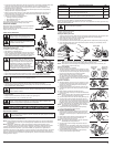
NOTE: SplitLine™ can only be used with the inner reel with the slotted holes. Single line can be used on
either type of inner reel. Use Figure 28 to identify the inner reel you have.
NOTE: Always use the correct line length when installing trimming line on the unit. The line may not
release properly if the line is too long.
Single Line Installation
Go To Step 8 for SplitLine™ Installation
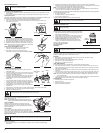
6. Take approximately 20 feet (6 m) of new trimming line, loop it
into two equal lengths. Insert each end of the line through one
of the two holes in the inner reel (Fig. 29). Pull the line through
the inner reel so that the loop is as small as possible.
7. Wind the lines in tight even layers, onto the reel
(Fig. 30). Wind the line in the direction indicated on the inner
reel. Place your index finger between the two lines to stop the
lines from overlapping. Do not overlap the ends of the line.
Proceed to step 11.
SplitLine™ Installation
8. Take approximately 10 feet (3 m) of new trimming line. Insert
one end of the line through one of the two holes in the inner
reel (Fig. 31). Pull the line through the inner reel until only
about 4 inches is left out.
9. Insert the end of the line into the open hole in the inner reel
and pull the line tight to make the loop as small as possible
(Fig. 31).
10. Before winding, split the line back about 6 inches.
11. Wind the line in tight even layers in the direction indicated on
the inner reel.
NOTE: Failure to wind the line in the direction indicated will cause
the cutting attachment to operate incorrectly.
12. Insert the ends of the line into the two holding slots (Fig. 32).
13. Insert the ends of the line through the eyelets in the outer
spool and place inner reel with spring inside the outer spool
(Fig. 33). Push the inner reel and outer spool together. While
holding the inner reel and outer spool, grasp the ends and pull
firmly to release the line from the holding slots in the reel.
NOTE: The spring must be assembled on the inner reel before
reassembling the cutting attachment.
14. Hold the inner reel in place and install the bump knob by
turning counterclockwise. Tighten securely.
INSTALLING A PREWOUND REEL
1. Hold the outer spool with one hand and unscrew the bump
knob clockwise. Inspect the bolt inside the bump knob to
make sure it moves freely (Fig. 25). Replace the bump knob if
damaged.
2. Remove the old inner reel from the outer spool (Fig. 25).
3. Remove the spring from the old inner reel (Fig. 25).
4. Place the spring in the new inner reel.
NOTE: The spring must be assembled on the inner reel before
reassembling the cutting attachment.
5. Insert the ends of the line through the eyelets in the outer
spool (Fig. 33).
6. Place the new inner reel inside the outer spool. Push the inner
reel and outer spool together. While holding the inner reel and
outer spool, grasp the ends and pull firmly to release the line
from the holding slots in the spool.
7. Hold the inner reel in place and install the bump knob by
turning counterclockwise. Tighten securely.
Fig. 25
Fig. 26
Fig. 27
Inner Reel
Spring
Outer Spool
Bump Knob
Bolt
Indexing Teeth
WARNING:
Never use metal-reinforced line, wire, chain or rope. These can break off
and become dangerous projectiles.
Fig. 28
For Use with
Single Line
ONLY
For Use with
SplitLine™ or
Single Line
Slotted
Holes
• Do not force the cutting attachment. Allow the tip of the line to do the cutting, especially along walls.
Cutting with more than the tip will reduce cutting efficiency and may overload the engine.
• Cut grass over 8 inches (200 mm) by working from top to bottom in small increments to avoid
premature line wear or engine drag.
• Cut from right to left whenever possible. Cutting to the left improves the unit's cutting efficiency.
Clippings are thrown away from the operator.
• Slowly move the trimmer into and out of the cutting area at the desired height. Move either in a
forward-backward or side-to-side motion. Cutting shorter lengths produces the best results.
• Trim only when grass and weeds are dry.
• The life of your cutting line is dependent upon:
• Following the trimming techniques
• What vegetation is being cut
• Where vegetation is cut
For example, the line will wear faster when trimming against a
foundation wall as opposed to trimming around a tree.
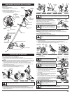
DECORATIVE TRIMMING
Decorative trimming is accomplished by removing all vegetation
around trees, posts, fences and more.
Rotate the whole unit so that the cutting attachment is at a 30°
angle to the ground (Fig. 22).
Fig. 22
Fig. 29
Loop
Fig. 30
Fig. 31
Loop
Fig. 32
Fig. 33
Spring
Holding Slots