


6
WARNING:
Operate this unit only in a well- ventilated outdoor area. Carbon monoxide
exhaust fumes can be lethal in a confined area.
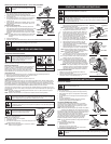
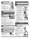
STARTING INSTRUCTIONS
STOPPING INSTRUCTIONS
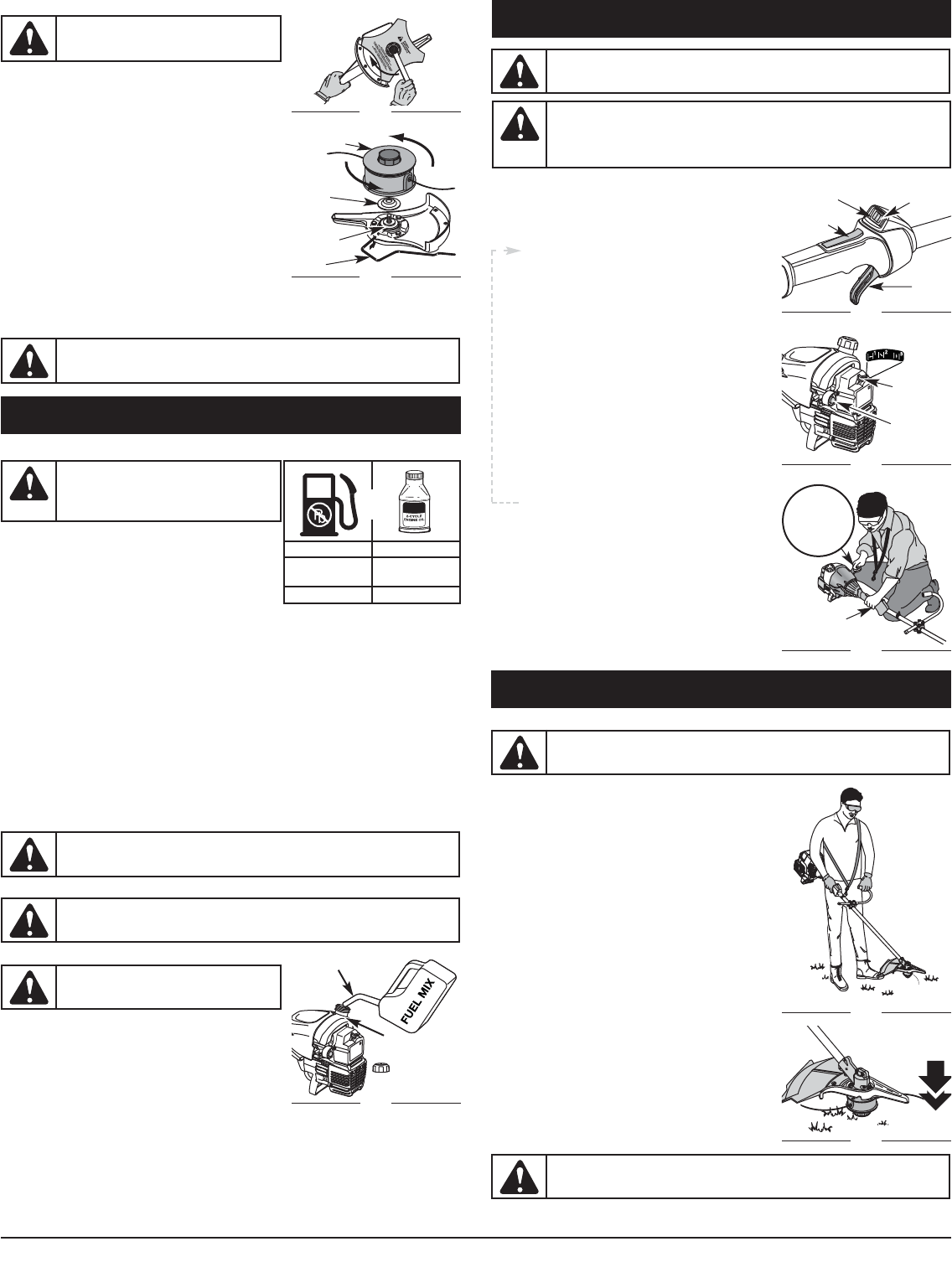
1. Release your finger from the throttle control. Allow the
engine to cool down by idling.
2. Press and hold On/Off Stop Control in the OFF (O) position
until engine comes to a complete stop (Fig. 17).
1. Mix gas with oil. Fill fuel tank with fuel/oil mixture. See
Oil and Fuel Mixing Instructions.
NOTE: There is no need to turn the unit on. The On/Off Stop
Control is in the ON ( I ) position at all times (Fig. 17).
2. Fully press and release the primer bulb 10 times,
slowly. Some amount of fuel should be visible in the
primer bulb and fuel lines (Fig. 18). If you can’t see
fuel in the bulb, press and release the bulb as many
times as it takes before you can see fuel in it.
3. Place the blue choke lever in Position 1 (Fig. 18).
4. Crouch in the starting position (Fig. 19), squeeze the
throttle lock-out and throttle control, and pull the
starter rope 5 times in a controlled and steady motion.
5. Place the blue choke lever in Position 2 (Fig. 18).
6. While squeezing the throttle lock-out and throttle
control, pull the starter rope in a controlled and steady
motion until the engine starts.
7. Keep the throttle lock-out and throttle control squeezed
and allow the engine to warm up for 15 to 30 seconds.
NOTE: Engine may take longer to warm up and reach
maximum operating speed at colder temperatures.
NOTE: Unit is properly warmed up when engine
accelerates without hesitation.
8. Once the engine is warmed up, place the blue choke
lever in Position 3 (Fig. 18). The unit is ready for use.
IF... the engine hesitates, return the blue choke lever to
Position 2 (Fig. 18) and continue warm-up.
IF... the engine does not start, go back to step 2.
IF... the engine fails to start after a few attempts, place the
blue choke lever in Position 3 and squeeze the throttle
control. Pull the starter rope 3 to 8 times in a controlled
and steady motion. The engine should start. If not, repeat.
IF WARM... If the engine is already warm, make sure the
On/Off Stop control is in the ON position and start the
unit with the blue choke lever in Position 2. After the
unit starts, move the blue choke lever to Position 3.
STARTING / STOPPING INSTRUCTIONS
Fig. 17
Stop/Off (O)
Fig. 18
Blue Choke
Lever
Fig. 19
Starting
Position
Start/On ( I )
Throttle
Control
Primer Bulb
Throttle Control
Trimmer
Equipped With
Spring Assist
Starting ™
WARNING:
Avoid accidental starting. Make sure you are in the starting position when
pulling the starter rope (Fig. 19). To avoid serious injury, the operator and unit must be
in a stable position while starting.
To avoid serious personal injury, ensure any Add-On being used is installed correctly and
secure before starting the unit.
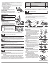
OPERATING INSTRUCTIONS
HOLDING THE TRIMMER
Before operating the unit, stand in the operating position (Fig. 20).
Check for the following:
• The operator is wearing eye protection and proper clothing
• With a slightly-bent right arm, the operator’s hand is holding
the shaft grip
• The operator’s left arm is straight, the left hand holding the D-
handle
• The unit is at waist level
• The cutting attachment is parallel to the ground and easily
contacts the grass without the need to bend over
ADJUSTING TRIMMING LINE LENGTH
The Bump Head™ cutting attachment allows you to release
trimming line without stopping the engine. To release more line,
lightly tap the cutting attachment on the ground (Fig. 21) while
operating the trimmer at high speed.
NOTE: Always keep the trimming line fully extended. Line release
becomes more difficult when the cutting line gets shorter.
Each time the head is bumped, about 1 inch (25.4 mm) of trimming
line releases. A blade in the cutting attachment shield will cut the
line to the proper length if any excess line is released.
For best results, tap the bump knob on bare ground or hard soil. If
you attempt a line release in tall grass, the engine may stall.
Always keep the trimming line fully extended. Line release
becomes more difficult when the cutting line gets shorter.
NOTE: Do not rest the Bump Head™ on the ground while the unit
is running.
Some line breakage will occur from:
• Entanglement with foreign matter
• Normal line fatigue
• Attempting to cut thick, stalky weeds
• Forcing the line into objects such as walls or fence posts
TIPS FOR BEST TRIMMING RESULTS
• Keep the cutting attachment parallel to the ground.
WARNING:
Always wear eye, hearing, foot and body protection to reduce the risk of
injury when operating this unit.
CAUTION:
Do not remove or alter the line cutting blade assembly. Excessive line
length will make the clutch overheat. This may lead to serious personal injury or damage
to the unit.
Fig. 20
Fig. 21
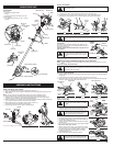
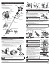
REMOVE THE CUTTING BLADE AND INSTALL THE CUTTING ATTACHMENT
Remove the Cutting Blade
1. Align the shaft bushing hole with the locking rod slot and
insert the locking rod into the bushing hole (Fig. 8).
2. Hold the locking rod in place by grasping it next to the boom
of the unit (Fig. 14).
3. While holding the locking rod, loosen the nut on the blade by
turning it clockwise with a 13 mm closed-end or socket
wrench (Fig. 14).
4. Remove the nut, blade retainer and blade. Store the nut and
blade together for future use in a secure place. Store out of
children’s reach.
Install the Cutting Attachment
5. Align the shaft bushing hole with the locking rod slot and
insert the locking rod into the shaft bushing hole (Fig. 8). Place
the blade retainer on the output shaft with the flat surface
against the output shaft bushing (Fig. 15). Screw the cutting
attachment counterclockwise onto the output shaft. Tighten
securely.
NOTE: The blade retainer must be installed on the output shaft in
the position shown for the cutting attachment to work
correctly.
6. Remove the locking rod.
7. Install the cutting attachment shield. Refer to Remove and Install the Cutting Attachment Shield.
Fig. 14
Clockwise
Fig. 15
Cutting
Attachment
Locking
Rod
Output Shaft
Bushing
Blade
Retainer
WARNING:
To avoid serious personal injury,
always wear gloves while handling or installing
the blade.
WARNING:
To avoid serious personal injury, the cutting attachment shield MUST be in
place at all times while operating the unit as a trimmer.
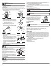
OIL AND FUEL INFORMATION
OIL AND FUEL MIXING INSTRUCTIONS
Old and/or improperly mixed fuel are the main reasons for the unit
not running properly. Be sure to use fresh, clean unleaded fuel.
Follow the instructions carefully for the proper fuel/oil mixture.
Definition of Blended Fuels
Today's fuels are often a blend of gasoline and oxygenates such
as ethanol, methanol, or MTBE (ether). Alcohol-blended fuel
absorbs water. As little as 1% water in the fuel can make fuel
and oil separate. It forms acids when stored. When using
alcohol-blended fuel, use fresh fuel (less than 60 days old).
Using Blended Fuels
If you choose to use a blended fuel, or its use is unavoidable, follow recommended precautions:
• Always use the fresh fuel mix explained in your operator's manual
• Always agitate the fuel mix before fueling the unit
• Drain the tank and run the engine dry before storing the unit
Using Fuel Additives
The bottle of 2-cycle oil that came with your unit contains a fuel additive which will help inhibit corrosion
and minimize the formation of gum deposits. It is recommended that you use our 2-cycle oil with this unit.
If unavailable, use a good 2-cycle oil designed for air-cooled engines along with a fuel additive, such as
STA-BIL® Gas Stabilizer or an equivalent. Add 0.8 oz. (23 ml.) of fuel additive per gallon of fuel according
to the instructions on the container. NEVER add fuel additives directly to the unit's fuel tank.
Thoroughly mix the proper ratio of 2-cycle engine oil with unleaded gasoline in a separate fuel can. Use a
40:1 fuel/oil ratio. Do not mix them directly in the engine fuel tank. See the table below for specific gas and
oil mixing ratios.
NOTE: One gallon (3.8 liters) of unleaded gasoline mixed with one 3.2 oz. (95 ml.) bottle of 2-cycle oil
makes a 40:1 fuel/oil ratio.
NOTE: Dispose of the old fuel/oil mix in accordance to Federal, State and Local regulations.
FUELING THE UNIT
1. Remove the fuel cap.
2. Place the gas container’s spout into the fill hole on the fuel
tank (Fig. 16) and fill the tank.
NOTE: Do not overfill the tank.
3. Wipe up any fuel that may have spilled.
4. Reinstall the fuel cap.
5. Move the unit at least 30 ft. (9.1 m) from the fueling source and
site before starting the engine.
NOTE: Dispose of the old fuel mixture in accordance to Federal,
State and Local regulations.
WARNING:
Gasoline is extremely flammable. Ignited vapors may explode. Always
stop the engine and allow it to cool before filling the fuel tank. Do not smoke while filling
the tank. Keep sparks and open flames at a distance from the area.
WARNING:
Add fuel in a clean, well ventilated outdoor area. Wipe up any spilled fuel
immediately. Avoid creating a source of ignition for spilt fuel. Do not start the engine until
fuel vapors dissipate.
MIXING RATIO - 40:1
UNLEADED GAS 2 CYCLE OIL
1 GALLON US
(3.8 LITERS)
3.2 FL. OZ.
(95 ml)
1 LITER 25 ml
+
WARNING:
Remove fuel cap slowly to avoid
injury from fuel spray. Never operate the unit
without the fuel cap securely in place.
CAUTION:
For proper engine operation and
maximum reliability, pay strict attention to the oil
and fuel mixing instructions on the 2-cycle oil
container. Using improperly mixed fuel can
severely damage the engine.
Fig. 16
Fuel Can Spout
Fuel Tank
Throttle
Lock-Out