


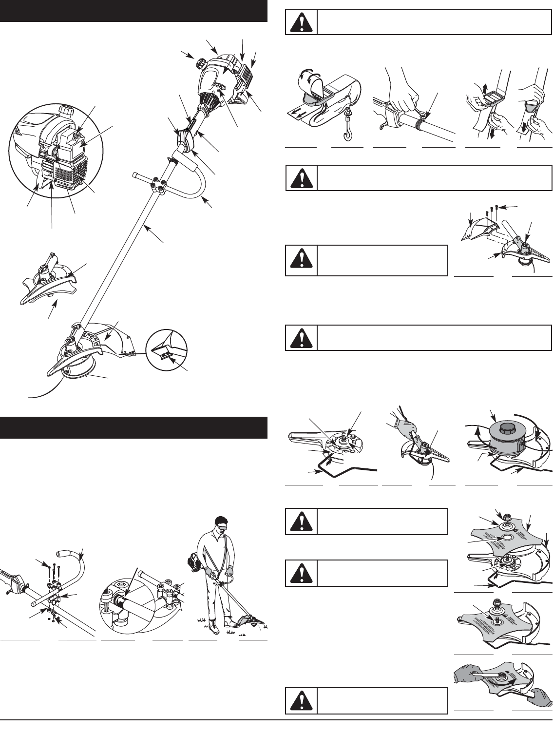
5
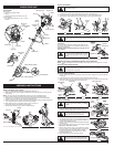
Cutting Attachment Shield
Fuel Cap
Cutting Attachment
Engine Stand
Muffler
Muffler Guard
Blue Choke Lever
Line Cutting Blade
On/Off Stop
Control
Blue Choke
Lever
KNOW YOUR UNIT
Spark Plug
APPLICATIONS
As a trimmer:
• Cutting grass and light weeds
• Edging
• Decorative trimming around trees, fences, etc.
As a brushcutter:
• Cut weeds and light brush up to 1/2” (1.3 cm) in
diameter
ASSEMBLY INSTRUCTIONS
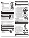
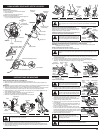
INSTALL AND ADJUST THE J-HANDLE
1. Place the J-handle between the top and middle clamp pieces (Fig. 1).
2. While holding the three pieces together, install the four (4) screws through the top clamp and into
middle clamp.
NOTE: The holes in the top and middle clamp will line up only when assembled correctly.
3. Place the clamps and the J-handle over the shaft housing and onto the bottom clamp.
4. Hold each hex nut in the bottom clamp recess with a finger. Start screws with a large Phillips
screwdriver. Do not tighten until you make the handle adjustment.
5. Slide the J-handle in or out until the arrow/white line on the decal touches the clamp assembly (Fig.
2). You must first loosen the screws if the handle is pre-installed.
6. While holding the unit in the operating position (Fig. 3), position the J-
handle to the location that provides you the best grip.
7. Tighten the clamp screws evenly, until the J-handle is secure.
Fig. 1
(4) Screws
Top Clamp
J-Handle
Bottom Clamp
Nuts
Middle
Clamp
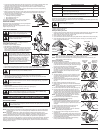
INSTALL THE HARNESS
1. Push the strap through the center of the buckle.
2. Pull the strap over the cross bar and down through the slot in the buckle (Fig. 4).
3. Put the harness on over head and onto shoulder. Snap it on to the support fitting (Fig. 5).
4. Adjust length to fit the operator’s size. Pull tab to lengthen, pull strap to shorten (Fig 6).
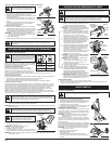
REMOVE AND INSTALL THE CUTTING ATTACHMENT SHIELD
Remove the cutting attachment shield when using the unit as
a brushcutter
Remove the cutting attachment shield from the shield mount by
removing the three (3) screws with a flat blade screwdriver (Fig. 7).
Store parts for future use.
Install the cutting attachment shield when using the unit as a
grass trimmer
Install the cutting attachment shield on the shield mount by
inserting the three (3) screws into the shield mount. Tighten securely with a flat blade screwdriver (Fig. 7).
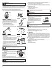
REMOVE THE CUTTING ATTACHMENT AND INSTALL THE CUTTING BLADE
NOTE: To make cutting blade removal and installation easier, place the unit on the ground or on a work
bench.
Remove the Cutting Attachment Shield
See Remove and Install the Cutting Attachment Shield.
Remove the Cutting Attachment
1. Align the shaft bushing hole with the locking rod slot and insert the locking rod into the shaft bushing
hole (Fig. 8).
2. Hold the locking rod in place by grasping it next to the boom of the unit (Fig. 9).
3. While holding the locking rod, remove the cutting attachment by turning it clockwise off of the output
shaft (Fig. 10). Store the cutting attachment for future use.
NOTE: The blade retainer under the cutting attachment will be used when installing the cutting blade.
Install the Cutting Blade
4. Place the cutting blade on the output shaft bushing (Fig. 11).
5. Make sure that the cutting blade is centered on the pilot step
and sitting flat against the output shaft bushing (Fig. 12).
6. Align the shaft bushing hole with the locking rod
slot and insert the locking rod into the bushing hole (Fig. 8).
7. Put the blade retainer and nut on the output shaft. Make sure
that the blade is installed correctly.
8. Tighten nut counterclockwise against the blade while holding
the locking rod:
• If using a torque wrench and an 13 mm socket tighten to: 325 -
335 in•lb, 27 - 28 ft.•lb, 37 - 38 N•m.
• Without a torque wrench, use a 13 mm closed-end or socket
wrench, turning the nut until the blade retainer is snug against
the shaft bushing. Make sure that the blade is installed
correctly, then rotate the nut an additional 1/4 to 1/2 turn
counterclockwise (Fig. 13).
9. Remove the locking rod from the locking rod slot.
Fig. 7
Fig. 11
Fig. 4
Fig. 5
Fig. 6
Support
Fitting
WARNING:
The cutting attachment shield should NOT be installed when operating the
unit with a blade. Remove the cutting attachment shield before removing or installing the
blade.
WARNING:
Always use the shoulder harness when using the cutting blade to avoid
serious personal injury.
Fig. 8
Fig. 9
Fig. 10
Support
Fitting
Cutting
Attachment
Shield
(3) Screws
Gear Housing
Shield Mount
WARNING:
To avoid serious personal injury,
the cutting attachment shield MUST be in place
at all times while operating the unit as a grass
trimmer.
WARNING:
The gear housing gets hot with use. It can result in injury to the operator.
The housing remains hot for a short time even after the unit is turned off. Do not touch the
gear housing until it has cooled.
Shaft Bushing
Hole
Output Shaft
Output Shaft
Bushing
Locking
Rod
Locking
Rod Slot
Cutting Attachment
Locking
Rod Slot
Locking Rod
Blade
Retainer
Shield
Mount
Locking
Rod
Cutting
Blade
Nut
Output Shaft
Bushing
Pilot
Hole
WARNING:
To avoid serious personal injury,
always wear gloves while handling or installing
the blade.
WARNING:
If the cutting blade is off-center,
the unit will vibrate and the blade may fly off,
causing possible serious personal injury.
Fig. 12
Pilot Step
Fig. 13
1/4-1/2 turn Counterclockwise
WARNING:
To avoid serious personal injury or
damage to the unit, do not start or operate this
unit with the locking rod in the locking rod slot.
Throttle Control
J-Handle
Shaft Grip
Air Filter/Muffler
Cover
Shaft Housing
Starter Rope Grip
Spark Plug
Primer Bulb
Muffler
Cutting Blade
Blade Shield
Mount
Fig. 2
Decal
Fig. 3
Throttle
Lock-Out