


67
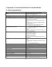
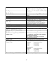
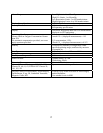
Scale Reference Bar A fixed 1 mV reference bar is displayed with the
top ECG waveform for scaling of the waveform.
This is provided in place of a standardizing voltage.
Lead Display Single, user selectable: I, II, III; or I, II, III, aVR,
aVL, aVF, V
Heart Rate Display Numeric
Waveform Display One or two rows (cascading) of ECG waveform
display
Leads Off Condition Detected and displayed (selected lead only)
Alarms High and Low Heart Rate
Alarm Ranges Heart Rate Low Limits: 21 to 245 beats/minute
Heart Rate High Limits: 25 to 249 beats/minute
Pulse Tone Constant frequency, ECG used alone;
Synchronized to SpO
2
pulse tone, ECG and SpO
2
used together, frequency varies with perfusion
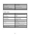
Input Impedance >2.5 Megohms at 10Hz
Input Protection Defibrillator and Electrosurgery protected
Defibrillator Recovery per EC13:1992 Clause
3.1.2.1a)
<8 seconds
Impedance Respiration/Leads Off Detection
Current per EC13:1992 Clause 3.1.2.1b)
50nA max for RA ,LA, LL, V; 200nA max for RL
Tall T Wave Rejection per EC13:1992 Clause
3.1.2.1c)
Rejects Tall T waves through 1.4 mV
Heart Rate Averaging Method per EC13:1992
Clause 3.1.2.1d)
Number of consecutively detected beats:
>12: Heart rate = 60/(average of last 12 detected
consecutive R-R intervals)
<12: Heart rate = 60/(average of the detected
consecutive R-R intervals)
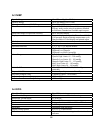
Response to Change in Heart Rate per EC13:1992
Clause 3.1.2.1f)
Increasing from 80 to 120 beats/minute: 3 sec
Decreasing from 80 to 40 beats/minute: 9 sec
Time to Alarm for Tachycardia per EC13:1992
Clause 3.1.2.1g)
Waveform 4(a)
Amplitude: Average time to alarm:
0.5 mV 6.21 seconds
1.0 mV 50.2 seconds
2.0 mV 10.96 seconds
Waveform 4(b)
Amplitude: Average time to alarm:
1.0 mV 50.3 seconds
2.0 mV 12.06 seconds
4.0 mV 6.40 seconds
Pacemaker Display per EC13:1992 Clause 3.2.9.12 Pacemaker signals displayed as captured.