


12
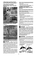
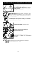
5. Wind the line evenly and tightly onto the
spool. Windin the direction of thearrows
found on the spool.
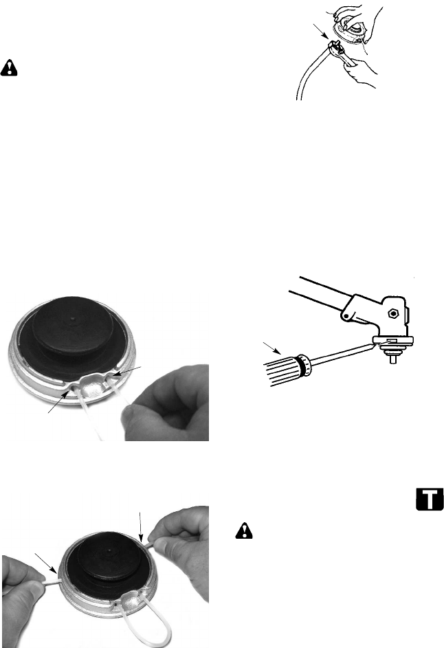
6. Pushthe lines intothe notches, leaving3
to 5 inches (7 -- 12 cm) unwound.
7. Insert the lines into the the exit holes in
the hub as shown in the illustration.
8. Align thenotches with the line exit holes.
9. Push spool into hub until it snaps into
place.
10. Pullthelinesextendingoutsideofthehub
to release the lines from the notches.
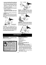
LINE REPLACEMENT
(Models W25CF, W25SF, W25CFK,
W25SFK)
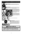
WARNING:
For models W25CB,
W25SB, W25CBK, W25SBK, use only 0.080
inch(2mm)diameterline.Othersizesoflinewill
not advance properly and willresult inimproper
cutting head function or can cause serious
injury. For models W25CF, W25SF, W25CFK,
W25SFK,useonly0.095inch(2.4mm)diame-
ter cut length line. Do not use other materials
such as wire, string, rope, etc. Wire can break
offduringcutting andbecomea dangerouspro-
jectile that can cause serious injury.
For unit to operate properly, the cutting line
should bereplaced whenline becomes worn
tolessthan3inches inlengthfromtheedgeof
each side of the cutting head.
1. Remove and discard worn line before
installing new line.
2. Clean entire surface of cutting head.
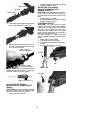
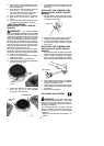
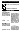
3. Insertendsoflineintothetwoguideholes
on front of cutting head.
Guide
Hole
Guide
Hole
4. Continue to feed line through the guide
holes until the line is fully extended
through the side exit holes.
Side Exit Hole
Side Exit
Hole
5. Pullendsoflineuntillineis tight.Correctly
installed line will be the same length on
both ends.
REPLACING THE TRIMMER HEAD
(Models W25CB, W25SB, W25CBK,
W25SBK)
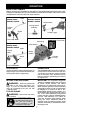
1. Hold the dust cup with a wrench to keep
theshaftfromturningwhileremovingand
installing trimmer head.
Dust Cup
2. Remove trimmer head by turning counter-
clockwise (looking from bottom of unit).
3. Thread replacement trimmer head onto
the shaft by turning clockwise. Tighten
until secure.
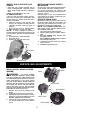
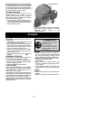
REPLACING THE TRIMMER HEAD
(Models W25CF, W25SF, W25CFK,
W25SFK)
1. Alignholeinthedustcupwiththeholeinthe
sideofthegearboxby rotatingthedustcup.
2. Insert a small screwdriver into aligned
holes. This will keep the shaft from turning
whileremovingandinstalling trimmerhead.
Screwdriver
3. While holding the screwdriver in position,
remove trimmer head by turning clockwise
(looking from bottom of unit).
4. Threadreplacementtrimmer headontothe
shaft by turning counterclockwise. Tighten
until secure.
5. Remove the screwdriver.
IDLE SPEED ADJUSTMENT
WARNING:
Keepothers away when
makingidlespeedadjustments. The trimmer
head will be spinning during this procedure.
Wearyourprotectiveequipment andobserve
all safety precautions.
The carburetor has been carefully set at the
factory. Adjustment of the idle speed may be
necessary if you notice any of the following
conditions:
S Engine will not idle when the throttle is re-
leased.