


10
ASSEMBLY
WARNING: If received assembled,
review allassembly steps toensure your unit
is properly assembled and all fasteners are
secure.
INSTALLING LINE TRIMMER
ATTACHMENT
CAUTION:
Whenremoving or installingat-
tachments, place theunit on aflat surfacefor
stability.
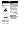
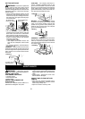
1. Loosen the coupler by turning the knob
counterclockwise.
Coupler
Knob
LOOSEN
TIGHTEN
2. Remove the shaft cap from attachment
(if present).
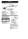
3. Position locking/release button of at-
tachment into guide recess o f coupler .
4. Push the attachment into the coupler
until the locking/release button snaps
into the primary hole.
5. Before using the unit, tighten the knob se-
curely by turning clockwise.
Coupler Primary Hole
Upper
Shaft
Locking/
Release
Button
Attachment
Guide Recess
WARNING: M ake sure the locking/
release button is locked in the primary hole
andthe knobis securely tightenedbefore o p -
eratingtheunit. Allattachments a redesigned
to be used in the primary hole.
For assembly of optional attachments (see
list o n page 4), refer to the ASSEMBLY s ec -
tion of the applicable attachment instruction
manual.
ATTACHING SHIELD
WARNING: The shield m ust be prop-
erly installe d.The shieldprovides pa rtialprotec-
tion from therisk of thrown objects to theopera-
tor and others and is equipped with a line l imiter
blade which cuts excess line to the proper
length. The line limiter blade (on underside of
shield) is sharp and can cut you.
For proper orientation of shield, see KNOW
YOUR UNIT illustration in the OPERATION
section.
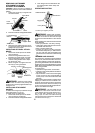
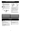
1. Remove wing nut from shield.
2. Insert bracket into slot as shown.
3. Pivot shield until bolt passes through
hole in bracket.
4. Securely tighten wing nut onto bolt.
Slot
Shield
Wing
Nut
Bracket
Line Limiter
Blade
PIVOT
ADJUSTING THE HANDLE
WARNING: Whenadjusting thehan-
dle, be sure itremains above the safety label
and below the m ark or arrow on the shaft.
1. Loosen wing nut on handle.
2. Rotate the handle on the shaft to an up-
right position; retighten wing nut.