


10
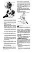
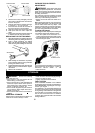
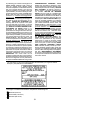
Hub
Line in Notch
Line in Notch
Line exit holes
5. Wind the line evenly and tightly onto the
spool. Wind in the directionof thearrows
found on the spool.
6. Push the lines intothe notches,leaving3
to 5 inches (7 -- 12 cm) unwound.
7. Insert the lines into the the exit holes in
the hub as shown in the illustrat ion.
8. Align the notches with the line exit holes.
9. Push spool into hub until it snaps into
place.
10. Pull thelines extendingoutsideof thehub
to release the lines from the notches.
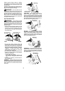
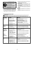
REPLACING THE CUTTING HEAD
1. Align hol ein thedust cupwi th thehole inthe
side of t he g earbox by rotating thedustcup.
2. Insert a small screwdrive r into aligned
holes. This wi ll keep the shaft from turning
while removingand installing t rimmer head.
Screwdriver
3. While holding the screwdriver in position ,
remove trimmer head by turning clockwise
(looking fr om bottom of u nit).
4. Thread replacement trimmer head onto the
shaft by turning co untercl ockwise. Tighten
until secure.
5. Remove the screwdriver.
CARBURETOR IDLE SPEED
ADJUSTMENT
WARNING: Keep others away when
making idle speed adjustments. The trimmer
head will be spinning during this procedure.
Wear your protective eq uipmentand o bserve
all sa fety precautions.
The carburetor has been carefully set at the
factory. Adjustments maybenecessary ifyou
notice any of the following conditions:
S Engi ne will not idle when the throttl e is re-
leased .
Make adjustments with the unit support edso
the cutt ing attachment is off the ground and
will not make contact with any object. Hold
theunit byhand whilerunningandmakingad-
justments. Keep all parts of your body away
from the cutting attachment and muffler.
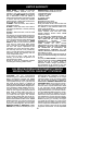
To adjust idle speed:
Allow enginetoidle. Adjustspeeduntilengine
runs without stalling (idle speed too slow).
S Turn idle speed screw clockwise to in-
creaseenginesp eedif enginestallsordies.
S Turn idle speed screw counterclockwiseto
decrease engine speed.
Air Filter Cover
Idle Speed Screw
If yourequire f urtherassistanceor areunsure
about performing this procedure, contact an
authorized service dealer or call
1--800--554--6723.
STORAGE
WARNING: Perform the following
steps after each use:
S Allow engine to cool, and se cure the unit
before storing or transporting.
S Store unit and fuel in a well ventilated area
where fuel vapors cannot reach sparks or
open flames from water heaters, electric
motors or switches, furnaces, etc.
S Store unit with all guards in place. Position
unit so t hat any shar p object cannot acci-
dentally cause injury.
S Store unit and fuel well out of the
reach of
children.
SEASONAL STORAGE
Prepareunit for storage atend of season or if
it will not be used for 30 days or m ore.
If your unitis t obe st ored f or aperiod oftime:
S Cl ean the e ntire unit before lengthy storage.
S Store in a clean dry area.
S Lightly oil external metal surfaces.
FUEL SYSTEM
Under FUEL ING ENGINE in the OP ERA-
TIONsectionof thismanual,see m essagela-
beled IMPOR TAN T regar ding the use of ga-
sohol in your engine.
Fuel stabilizer is an acceptable alternative in
minimizing the fo rmation offuel gumdeposits
during storage. Add stabilizer to the gasoline
in the fuel t ank or fuel storage container. Fol-
low the m ix instructions found on stabilizer
container. Runengine at least5 minutes after
adding stabilizer.