5
ASSEMBLY
WARNING: Stop the unit and dis-
connect f r om the power source before
openi n g the in let cover or attem pting to in-
sert or remove the inlet restrictor , blower
tube , nozzle, or vacu um tubes. The motor
mustbe stoppedand t heimpel l erbladesno
longer turning to avoid serious injury from
the rot at i ng blades.
WARNING: If you receive your
unit assembled, check ea ch step to in-
sure your unit is properly assembled and
all fasteners are secure. Follow all safety
information in the manual and on unit.
S A standard screwdriver is required for
assembly.
BLOWER ASSEMBLY
NOTE: Assembly intructions for using
your unit as a vacuum follow this section.
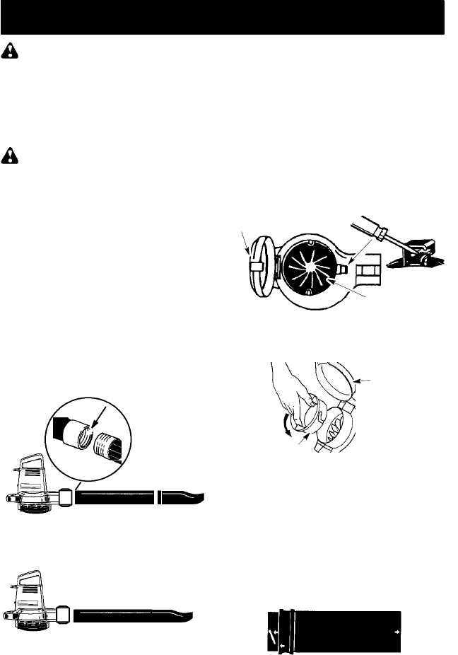
ATTACHINGTHE BLOWER TUBEAND
NOZZLE
1. Insert the bl ow er tube int o the blow er
outlet.
2. Twistthe blowertube clockwise untilit
is firmly seated in the blower outlet.
3. Twist the nozzle into the end of the
blower tube until it is firmly seated.
Make sure the nozzle points upward.
Blower Tube Nozzle
Blower o utlet
For Model 2695 only, the blower exten-
sion tube and nozz le are combined into
one component.
Blower Tube/Nozzle
VACUUM ASSEMBLY
(Some models)
NOTE: Assembly instructions for using
your unitas ablower are explained in the
previous section.
If you have already assembled your unit
for use as a blower, remove the blower
tube and nozzle.
REMOVE THE INLET RESTRICTOR
An inlet restrictor is used when using your
unit as a blower . This restrictor is not used
during vacuum use and must be rem oved
during a ssembl y fo r vacuum use.
NOTE: Besure to keep the inletrestrictor
for using your unit as a blower.
1. En sure unit is stopped and extensi on
cord is unplugged.
2. Open the inlet cove r by inserting the
tip of a screwdriver into the latch area
on the vacuum inlet cover. Gently tilt
handle ofscrewdrivertoward the front
oftheunitwhilepullingupon thevacu-
um inlet cover with your other hand.
Impeller
Latch Area
Vacuum Inlet Cover
3. T urn the inlet restrictor counterclock-
wise and r emove i tfromthe unit . D onot
close t he inlet door . You wil l next attach
the vacuum tubes.
Inlet
Restrictor
Vacuum
Inlet Cover
ATTACHING TH E VACUUM TUBES
There ar e 2 vacuum tubes, an upper and
lowertube.Theuppertubeis cutstraighton
both ends and attaches to the blower unit .
The l ower tube att aches to the upper tube,
and has an angled end that you point to-
ward t he gr ound during vacuum use.
1. Ens ure unit is stopped and extension
cord is unplugged.
2. Lo cate the arrows on the upper vacu-
um tube and on the vacuum inletarea
of the unit.
Upper Vacuum Tube
3. While holding the inlet cover open, align
the arrows and insert t he vacuum tube
into the opening. Twist t he tube cl ock-
wiseuntilitisseated.Asecondarrowon
the vacuumtube will align with t he arrow
on t heunitonce t he t ubeis t wi stedcom-
pletel y i nto pl ace.


