


-- 3 --
MAINTAIN YOUR UNIT PROPERLY
D Have all maintenance other than the rec-
ommended pr ocedures described inthe in -
struction manual performed by an autho-
rized service dealer.
D Disconnect spark p lug bef ore performing
maintenance except for carburetor adjust-
ments.
D Use only recommended Weed EaterŽ re-
placement parts; u se of any other parts
may voidyour warranty andcausedamage
to your unit.
D Empty f uel tank be fore s toring the unit. Use
upfuelleftin carburetor by starting engine and
letting it run unt il it stops.
D Do not use any accessory or attachment
other than those recommended by manufac-
turer for use with your unit.
D Do notstore theunit or fuel ina closed area
where fuel vapors can reach sparks or an
open flame f rom hotwater heaters, e lectric
motors or switches, furnaces, etc.
D Store in a dry area out of reach of children.
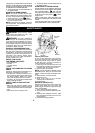
SPECIAL NOTICE: E xposure to vibra-
tions through prolonged useof gasoline pow-
ered hand tools could cause blood vessel o r
nerve damage in the fingers, hands, and
joints of people prone to circulation disorders
or abnormal swelling. Prolonged use in cold
weather has beenlinked toblood vesseldam-
age inotherwise healthy people.If symptoms
occur such as numbness, pain, loss of
strength, change in skin color or texture, or
loss of feeling in the f inge rs, hands, or joints,
discontinue the u se of this tool and seek
medical attention. An antivibration system
does not guarantee the avoidance of these
problems. Users who operate power tools on
a continual and regular basis must monitor
closely theirphysicalconditionand thecondi-
tion of this tool.
SPECIAL NOTICE: T his unit is equipped
with a temperature limiting muffler and spark
arresting screen which meets the require-
ments o fCalifornia Codes 4442and 444 3. All
U.S. forest land and the states of California,
Idaho, Maine, Minnesota, New Jersey, Ore-
gon, and Washington require by law that
many internal combustion engines be
equippedwithasparkarresting screen. Ifyou
operateinalocalewheresuch regulations ex-
ist, youare legallyresponsiblefor maintaining
the operating conditionoftheseparts. Failure
to do so is a v iolation of the law . R efer to the
MAINTENANCE section for information on
maintenance o f the muffler and spark arrest-
ing screen.
ASSEMBLY
WARNING: T his unit is intended for
blower use only. Do not att em pt to open inlet
cover.Openedor damagedinletcover canre-
sult inserious injury.Discontinue useof blow -
er immediatelyif inletcover becomes opened
or damaged. Take unit to your nearest autho-
rized service dealer for repair .
WARNING: If you receive your unit
assembled, check each step to insure your
unit is properly assembled and all f asteners
are s ecure. Follow all safety information in
the manual and on the unit.
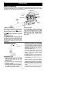
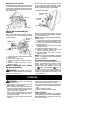
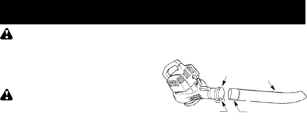
BLOWER TUBE ASSEMBLY
1. Align the rib on the blower tube with the
groove in the blower outlet; slide t he tube
into place.
NOTE: Knob m ustbe loose enoughto allow
blower tube to be inserted i n blower out let.
Loosen knob by turning counterclockwise.
Blower
Tube
Blower
Outlet
Rib
Groove
2. Secure thetubeby turning the knobclock-
wise.
3. Toremove thetube,turnthe knobcounter-
clockwise to loosen the tube; r emove the
tube.