


7
NOTE:
The dust cup is located on the gear-
box and not inthe parts bag. All otherfastening
hardw are mentioned in t he following assembly
steps is located in the parts bag.
S
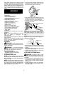
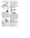
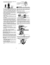
Leave the dust cup on the gearbox.
S
Install the blade and the retaining washer
over the threaded shaft extending from the
gearbox.
NOTE
:
It may be necessary to
remove a plastic protective covering from
the threaded shaft before installing these
parts.
S
Make sure the raised part of the retaining
washer is facing the gearbox and the raised
area fits into the hole in the center of the
blade (see illustration).
S
Slide the blade and retaining washer ont o
the shaft of the gearbox.
S
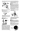
Now place the cupped washer onto the
shaft. Make sure the cupped side of the
washer is toward the blade.
S
Install the blade nut by threading onto the
shaft counterclockwise.
Shield
Blade
Retaining
Washer
Dust Cup
Cupped
Washer
Nut
Threaded
Shaft
NOTE:
Make sure all parts are in place as il-
lustrated, and the blade is sandwiched be-
tween the dust cup and the retaining washer.
There should be no space between the blade
and the dust cup or the retaining washer .
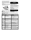
S
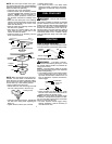
Push in locking lever and hold.
S
Rotate blade nut until the locking lever falls
into one of the grooves in the dust cup.
Locking Lever
S
Continueto holdinlocking lever. This w illkeep
the shaft fr om turning while tightening t he
blade nut.
S
Tighten blade nut firmly with a wrench.
S
Release locking lever.
S
Turn blade by hand. If the blade binds
against the shield, or appears to be uneven,
the blade is notcentered, and you must rein-
stall.
FUEL YOUR UNIT
WARNING:
Remove fuel cap slowly
when refueling.
This engine i s certified t o operate on unleaded
gasoline. Gasoline must be mix ed with a good
quality 2-cycle air- cooled engine oil designed to
be mixed at a ratio of 40:1. Poulan/Weed Eater
brand oil is recomm ended. (A 40:1 ratio i s ob-
tained bymixing 3.2ounces of oil with 1gallon o f
unleaded gasoline). When mixing fuel follow the
instructions printed o n the container. Always
read and follow the safety rules under FU EL
SAFETY.
STARTING
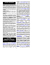
HOW TO STOP YOUR UNIT
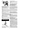
To stop the engine, move the ON/OFF switch
to the OFF position (toward the cutting head).
Throttle Trigger
ON/OFF
Switch
ON
OFF
STARTING YOUR ENGINE
WARNING:
The blade or trimmer
head will turn while starting the engine. Avoid
any contact with the muffler. A hot muffler can
cause serious burns.
NOTE:
A special f eature called the “ throttle
lock” holds the throttle trigger in t he depressed
position during starting.
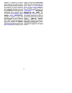
S
Lock throttle trigger into the starting postion
by first pressing the lock--out lever on the
top of the control handle. While the lock--out
lever is depressed, squeeze and hold the
throttle trigger.
Throttle Trigger
Lock--out
Lever
Lock Button
S
Before releasing the throttle trigger, press
the lock button. While this button is still de-
pressed release the throttle trigger.
NOTE:
This should allow the throttle trigger
to remain in the depressed position for start-
ing. You may want to practice this a few times
before you first start the unit.
S
DO NOT squeeze throttle trigger during
starting; otherwise, it will be necessary to
reset the throttle lock.