


5
S
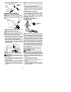
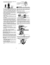
Insert screws and hand tighten only. These
screws will be tightened later.
Bracket Cover
Screw
Mounting
Bracket
Handlebar
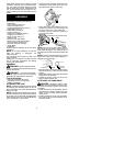
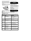
ATTACHING THE CONTROL
HANDLE TO THE HANDLEBAR
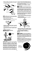
NOTE:
Make sure the wire going to the con-
trol handle i s routed below the tube and re-
mains o n the right side of the handlebar and
the tube.
Screw Hole
Screw
S
Slide handle onto t he right side of the han-
dlebar and align the screw hole.
S
Insert screw and tighten securely.
NOTE:
Make sure the control handle is on
the right side of the unit as shown in the il-
lustration below, and the ON/OFF switch is lo-
cated on the top of the control handle.
S
Adjust the handlebar to the proper position
and tighten the two screws you left loose
during handlebar assembly. Make sure
these screws are securely tightened.
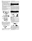
S
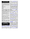
After attaching the control handle and tight-
ening the handlebar, route the wire from the
control handle through the slit in the bottom
of the foam grip.
Slit
Wire
Foam Grip
ASSEMBLY OF SHOULDER STRAP
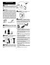
WARNING:
Propershoulderstrapand
handlebar adjustments before starting the en-
gine are requir ed.
S
Tr yon shoulderstrap andadjust forfit andbal-
ance before starting the engine or beginning a
cutting operation.
S
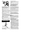
Insert your right arm and head through the
shoulder strap andallow it t orest onyourleft
shoulder. Make sure the danger sign is on
your back and the hook is t o the r ight side of
your waist.
NOTE:
A one-half twist is built in theshoulder
strap to allow the strap to rest flat onthe shoul-
der.
S
Adjust the strap, allowing t he hook to be
about 6 inches below the waist.
S
Fasten the strap hook to the clamp located
between the foam grip and the m ounting
block and lift the tool to the operating posi-
tion.
CONFIGURING YOUR UNIT
Yo u can configure your unit using a cutting
head for g rass and light weeds, or a brush
blade for cutting saplings and similar size ma-
terial. Go to the section for the desired
configuration and follow the instructions for
assembling your unit.
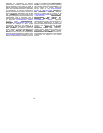
ASSEMBLY INFORMATION --
TRIMMER HEAD
TRIMMER
HEAD
NOTE:
Remove the blade and metal shield
before attaching the plastic shield and trimmer
head. To remove blade, push in locking lever
and hold. Rotate blade nut until the locking le-
verfalls into oneofthegrooves in the dustcup.
Continue to hold the locking lever. This will
keep theshaft from turning while loosening the
blade nut. Remove b lade nut byturning clock-
wise. Release locking lever. Remove both
washers and blade. To remove metal shield,
loosen and remove the four mounting screws.
See ATTACHING THE METAL SHIELD and
INSTALLING THE METALBLADE for illustra-
tions. Be sure to store al l parts and instruc-
tions for future use.
ATTACHING THE PLASTIC SHIELD
AND TRIMMER HEAD
WARNING:
The shield must be pr op-
erly installed. The shield provides partial protec-
tion from the risk of throw n objects to the opera-
tor and others and is equipped with a line limiter
which cuts excess line to the proper length. The
line limiter (on under side of shield) is sharp and
can cut you.
S
Remove wing nut from shield.
S
Insert bracket into slot on shield.
S
Pivot shield until bolt passes through hole in
bracket.
S
Tighten the wing nut securely.
S
If yourunithas aplastic coveroverthe t hreads
on the threaded shaft, r emove the covering to
expose the threads.