


4
ing condition of these parts. Failure to do sois
a violation of the law. For normal homeowner
use, the muffler and spark arresting screen
will not require any service. After 50 hours of
use, we recommend that your muffler be ser-
viced or replaced by your Authorized Service
Dealer.
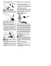
ASSEMBLY
CARTON CONTENTS
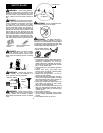
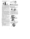
Check car ton contents for the following:
S
brushcutter
S
tube mounting screws (2)
S
tube mounting nuts (2)
S
control handle mounting screw (1)
S
handlebar screws (2)
S
blade shield screws (4)
S
cupped washer (1)
S
large nut for installing blade (1)
S
long hex key wrench (1)
S
short hex key wrench (1)
S
bracket cover
S
shield for use with blades
S
shield for use with trimmer head
S
semi-automatic trimmer head
S
shoulder strap with warning
S
brush blade
S
handlebar
Examine parts for damage. Do not use dam-
aged parts.
NOTE:
If you need assistance or find that
parts are missing or damaged, call
1-800-554-6723.
It is normal for the fuel filter to rattle in the
empty fuel tank.
Finding fuel or oil residue on muffler is normal
due to carburetor adjustments and testing
done by the manufacturer.
ASSEMBLY
WARNING:
Always stop unit anddis-
connect spark plug before performing any as-
sembly procedures.
WARNING:
If received assembled,
repeat all steps to ensure your unit is properly
assembled and all fasteners a re secure.
TOOLS REQUIRED
S
2 hex key wrenches (provided)
S
adjustable wrench or large pliers
S
phillips screwdriver
ATTACHING THE TUBE
NOTE:
Illustr a tion s with in this se c tion will h elp
in identifying the assembly steps. Be sure to
rea d each section and revie w the illustra tio n s ,
before you begin.
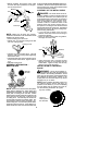
NOTE:
Adrive shaft is located inthe center of
the tube. Make sure this shaft does not fall out
of the tube. Dirt on the shaft will significantly
reduce the life of the unit. If this shaft falls out,
clean, relubricate , and re-install.
S
Insert the 2 tube assembly screws and nuts
as illustrated. Keep loose at this t ime, you
will tighten them during a later step.
S
Some units may include aplastic coverover
the end of the tube. If your unit includes any
covering, remove the cover at this time.
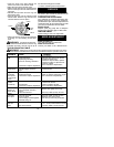
S
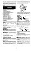
Pull about 1/2 inch of the drive shaft out of
the inside of the tube.
Pull about 1/2 inch from tube
Tube
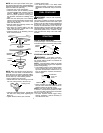
NOTE:
The end of the dr ive shaft is square.
This square end fits inside a square hole in a
shaft i nside the engine. Look inside the end of
theengineandyou w illseethesquarehole inthe
sha ft.
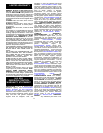
NOTE:
The end of the tube has agroove that
aligns with a ridge in the engine opening. Lo-
cate the groove and ridge.
GrooveRidge
S
Align the groove in the tube with the ridge in
the engine opening. Insert the tube into the
opening.
S
Firmly push the tube into engine until it w ill no
longer go into the opening.
S
Tighten the screws, using one of the hex
keys provided with the unit.
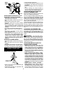
ATTACHING THE HANDLEBAR
DANGER:
The barrier portion of the
handlebar must be installed as shown to pro-
vide a barrier between operator and the spin-
ning blade.
S
Locate the decal on the handlebar. This de-
cal includes two arrows. Position t he han-
dlebar on t he mounting bracket between
these arrows.
S
Position the bracket cover over the handle-
bar. Again make sure the handlebar is be-
tween the arrows.