8
WATLOW Series 733/734 Service Manual
Install & Wire, Chapter 1
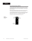
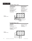
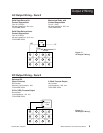
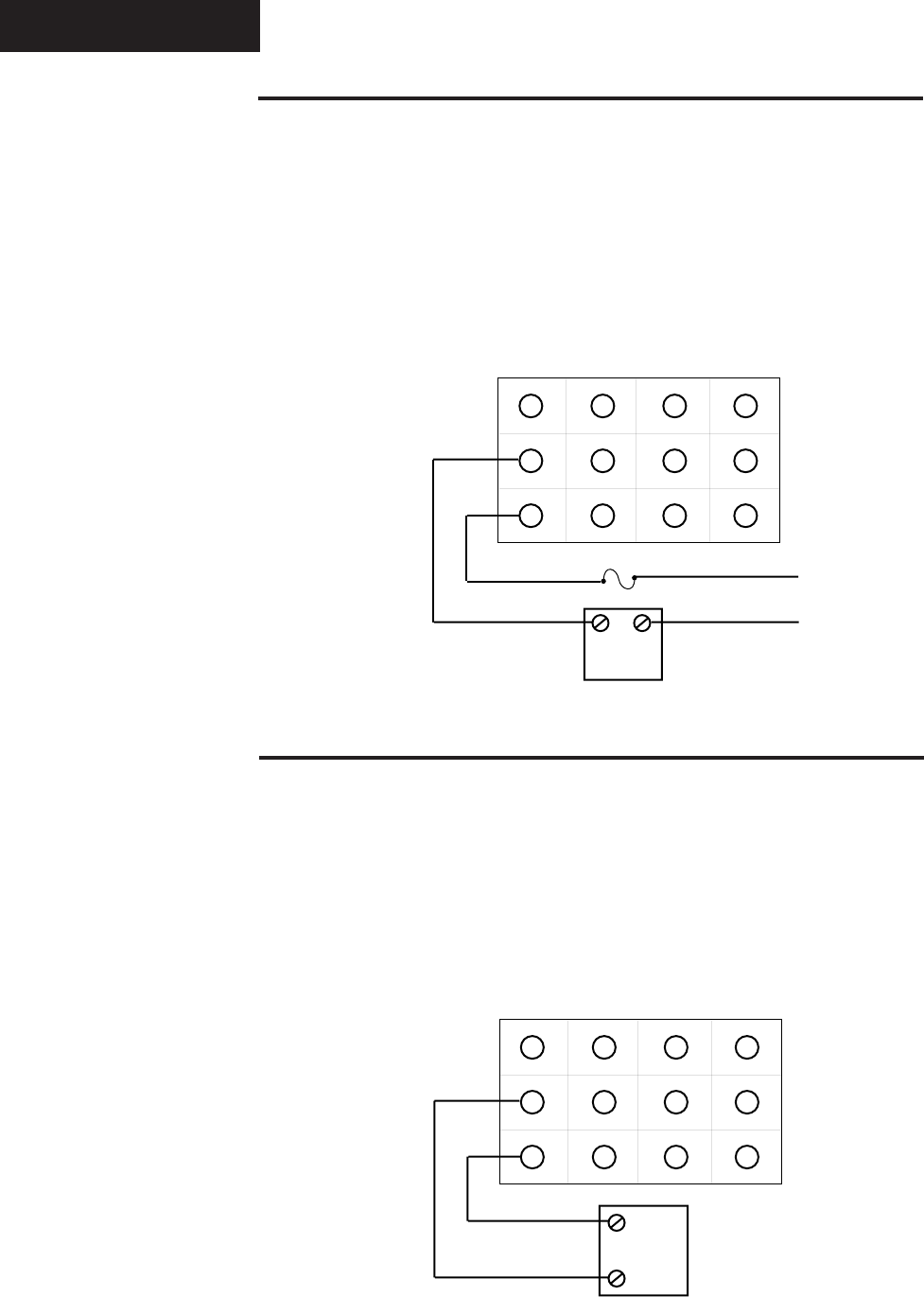
Output 1 Wiring
Figure 14 -
DC Output 1 Wiring.
Figure 13 -
AC Output 1 Wiring.
1
2
3
4
5
6
7
8
9
10
11
12
-
External
Load
+
-
+
1
2
3
4
5
6
7
8
9
10
11
12
External
Load
COM
L1
L2
Fuse
AC Output Wiring - Zone 1
Solid State Relay
with
Mechanical Relay
with
Contact Suppression Contact Suppression
Form A, 0.4 Amps Form A, 1 Amp
Off state impedance: 20K max. Off state impedance: 20K min.
73XX-XBXX-XXXX 73XX-XDXX-XXXX
Solid State Relay
without
Solid State Relay
without
Contact Suppression Contact Suppression
Form A, 0.4Amps Form A, 1 Amp
Off state impedance: 31M max. Off state impedance: 20k max.
73XX-XKXX-XXXX 73XX-XEXX-XXXX
DC Output Wiring - Zone 1
Switched DC
(Open Collector) 4-20mA Process Output
Non-isolated Non-isolated
Minimum load resistance: 500 Load impedance: 600 max.
73XX-XCXX-XXXX 73XX-XFXX-XXXX
0-5V
ÅÅ
ÅÅ
Å (VDC) Process Output
Non-isolated
Load impedance: 10K min.
73XX-XHXX-XXXX


