


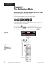

Calibration, Chapter 5
29
WATLOW Series 733/734 Service Manual
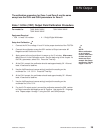
0-5V Output
˜
NOTE:
Before calibration
on an installed
control, make sure
all data and para-
meters are docu-
mented. See Setup
and Service Tables,
Pages 16 and 19.
The calibration procedure for Zone 1 and Zone 2 are the same
except use the Ot2L and Ot2H parameters for Zone 2.
Zone 1 0-5V
ÎÎ
ÎÎ
Î (VDC) Output Field Calibration Procedure
For model #'s: 73XX-XHXX-XXXX 73XX-XXHX-XXXX
73XX-XHHX-XXXX
Equipment Required
• 20K 1/4 watt 10% resistor. • 4 - 1/2 digit Digital Multimeter.
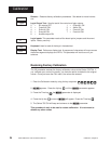
Setup And Calibration ˜
1. Connect the AC line voltage L1 and L2 to the proper terminals of the 733/734.
2. Connect the multimeter across the 20K resistor to Output connector #2
Negative and #3 Positive for Zone 1.
3. Apply power to the unit and allow it to warm up for 15 minutes. After warm-
up put the unit in the Calibration mode. See the beginning of this chapter At
the CALy parameter, select OUt. Press the Time key.
4. At the Ot1L prompt, the multimeter should read approximately 0V. Allow at
least 10 seconds to stabilize.
5. Use the Up/Down keys (reverse acting) to adjust the reading on the
multimeter for - 0.2 ± 0.1V. Press the Time key.
6. At the Ot1H prompt, the multimeter should read approximately 5V. Allow at
least 10 seconds to stabilize.
7. Use the Up/Down keys (reverse acting) to adjust the reading on the
multimeter for 5.2V ± 0.1V.
8. For dual 0-5V output control, connect the multimeter across the 20K resistor
to Output connector #4 Negative and #1 Positive. Use regular 20 - 24 gauge
wire. Repeat steps 4 through 7 using the Ot2L and Ot2H prompts.