


Calibration, Chapter 5
27
WATLOW Series 733/734 Service Manual
T/C-Process Input
˜
NOTE:
Before calibration
on an installed
control, make sure
all data and param-
eters are
documented. See
Setup and Service
Tables, Pages 16
and 19.
˜
NOTE:
Always press the
Time key to advance
to the next param-
eter before chang-
ing the calibration
equipment.
˜
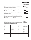
Thermocouple/Process Input Field Calibration Procedure
For model #: 73XX-6XXXX-XXXX
Equipment Needed
• Type "J" Reference Compensator with reference junction at 32°F/0°C
OR
Type "J" Thermocouple Calibrator set at 32°F/0°C.
• Precision millivolt source, 0-50mV min. range, 0.01mV resolution
• Precision voltage source 0-10 volt minimum range with 0.001 volt resolution.
• Precision current source 0 - 20mA minimum range with 0.001 volt resolution.
Setup And Calibration ˜
1. Connect the AC line voltage L1 and L2 to the proper terminals.
2. For Zone 1, connect the millivolt source to Terminal #2 Positive and Terminal #3
Negative on the Series 733/734 terminal strip. Use regular 20-24 gauge wire.
For Zone 2, connect the voltage source to Terminal #5 Positive and Terminal #6
Negative on the Series 733/734 terminal strip. Use regular 20-24 gauge wire.
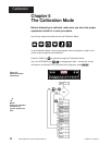
3. Apply power to the unit and allow it to warm up for 15 minutes. After warm-up put
the unit in the CAL menu. See the beginning of this chapter.
4. At the CALy parameter, select ALL. At the InLO prompt, enter 0.00 mV from the
millivolt source to the control for each zone. Allow at least 10 seconds to stabilize.
Press the TIme key.
5. At the InHI prompt, enter 50.0mV from the millivolt source for Zone 1. For Zone 2,
enter 10.00V from the voltage source. Allow at least 10 seconds to stabilize.
Press the Time key.
6. At the nAHI prompt, remove the voltage source from Zone 2. Connect the current
source to Terminal #6 Positive, and Terminal #4 Negative. Enter 20.00mA from
the current source. Allow at least 10 seconds to stabilize. Press the Time key.
7. At the tc prompt, disconnect the millivolt source, and connect the reference
compensator or t/c calibrator to Terminal #2 Positive, and Terminal #3 Negative for
Zone 1. If using a compensator, turn on and short the input wires. If using "J"
calibrator, set to simulate 32°F/0°C. Allow 10 seconds for the control to stabilize.
To conclude the t/c calibration, press the Time key to advance through the
Calibration mode. To continue calibrating your outputs, press the Time key once.
The unit will leave the Calibration mode if 1 minute passes between key activations
and retains all changed values.