


Page 12
WATERPIK TECHNOLOGIES INC.
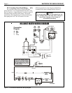
20. Connect the white wire labeled PS to the pressure
switch and the other white wire to its original
location on the Fireman's switch.
21. Reinstall the drain plugs and tighten securely.
Replace jacket/plug grommets.
22. Install the flue collector assembly. Be sure the
front and rear panels of the flue collector are
installed into the grooves on the front and rear
combustion chamber heat shield panels. Be sure
the sheet metal panels are not pinching any wires.
23. Attach the flue collector hold down clamps to the
clips located under the two center header bolts.
24. Replace the gap closures and tighten the screws
securely.
25. Double-check to make sure the wiring is not
pinched against sharp edges, or resting on the flue
collector assembly.
26. Reinstall rainshield assembly.
27. Replace the top assembly. Make sure the tabs are
outside the heater jacket. Fasten the top assembly
with the hex-head screws.
28. Install plastic tie wraps on wiring in the vestibule
(controls compartment).
29. Install heater door.
30. Reinstall the vent cap or drafthood, if one was
removed.
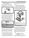
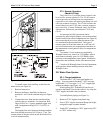
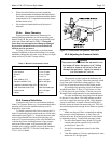
2G-3. Check Valve Installation
Install a check valve if there is any chance of back-
siphoning when the pump stops. Do not install any other
valve in the piping between the heater outlet and the
pool, unless it is being used as a diverter valve.
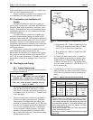
2G-4. Chlorinators, Ozone Generators,
and Sanitizing Chemicals
The Waterpik Laars Lite 2 heater is manufac-
tured with materials that are not compatible with high
concentrations of ozone, chlorine, bromine, or other
sanitizing chemicals. Heater damage caused by exces-
sive chemicals or improper ozonization is not covered
by the Waterpik Laars warranty. Be sure to adhere to
the following:
When ozone is injected upstream of the heater,
install an offgas mixing chamber, or an ozone
bypass system between the heater and the ozone
injector to prevent ozone and air from entering
the heater.
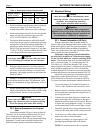
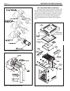
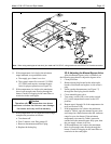
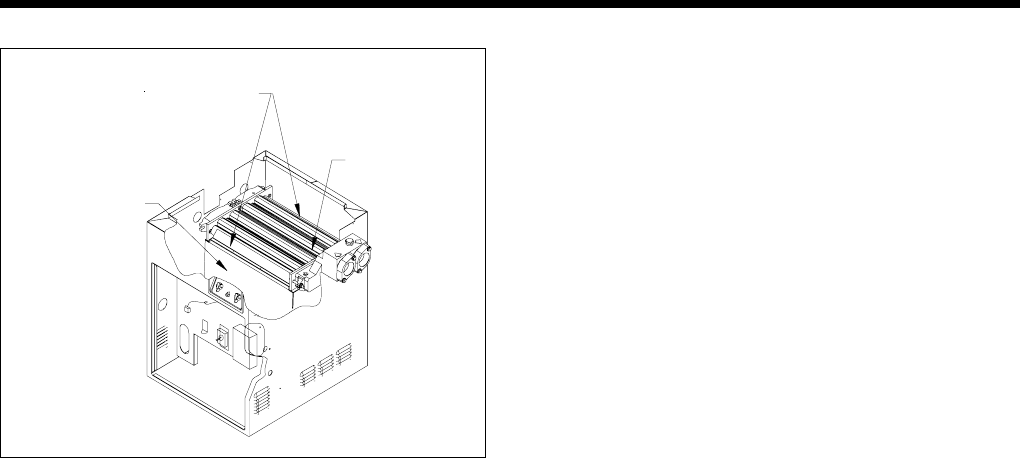
13. Lift the heat exchanger assembly out of the
heater. Reinstall heat exchanger 180 degrees
(inlet/outlet header left) from it's original posi-
tion.
14. After replacing the heat exchanger into the heater,
the end baffles must be replaced. Each one is
held in place by two screws which mount to the
top of the combustion chamber wall. Reinstall the
baffles on the front and rear of the heat exchanger
before continuing with the "Reversible Water
Connections" procedure.
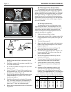
15. Remove pressure switch retainer (plastic cable
clamp) from the inner panel (allow pressure
switch to float).
16. On U.S. models reroute pressure switch tube and
thermostat bulb assembly through hole in left side
of vestibule cover in reverse order. Canadian
models have no cover on the left side of the
vestibule. Relocate the pressure switch tube and
temperature sensor through the open side of the
vestibule.
17. Reinstall the temperature sensing bulb in the
header, and fasten it with the retainer bracket and
screw.
18. Reinstall the compression fitting at end of pres-
sure switch tube into inlet/outlet header and
tighten the fitting.
19. Route the white wiring from the high limit
switches beside the heat exchanger and down to
the original location following the pressure switch
tubing. Secure white wires to the pressure switch
tube with plastic wire ties.
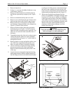
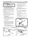
Figure 16. Heat exchanger and end baffles.
Combustion
Chamber Wall
Heat Exchanger
End Baffles
Heat Exchanger