


Page 8
WATERPIK TECHNOLOGIES INC.
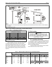
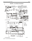
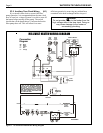
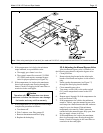
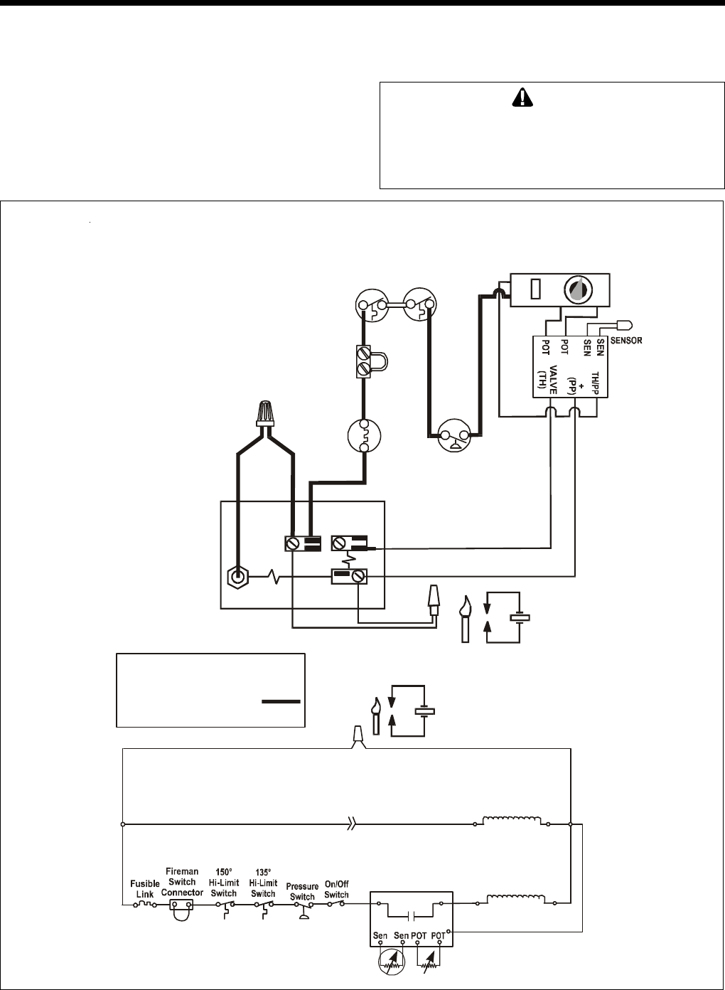
Figure 7. LG Connection/Schematic Wiring Diagram
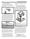
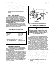
2F-2. Auxiliary Time Clock Wiring (LD)
If you install a time clock to control the filter
pump operation, it is recommended that the time clock
have its own low voltage (Firemans) switch to turn off
the heater before turning off the pump. The switch
should shut off the heater about 15 minutes before the
filter pump shuts off. This will allow for a more
efficient operation by removing any residual heat
contained in the heat exchanger back to the pool.
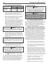
Caution
Do not provide power to the heater from the
high voltage side of the time clock. Doing so
may cause damage to the heater or
surrounding plumbing.
0, //,92/7+($7(5:,5,1*',$*5$0
Y
Connection
Diagram
BK
TH
PP
Y
Y
W
PP/TH
Pilot
Gen
R
W
Piezo
Sparker
Y
W
H0166000G
Pilot
Piezo
Sparker
R
Y
Y
BK
PP
PP
W
PP/TH
Valve
Operator
Coil
W
Y
To Pilot
Generator
Pilotstat
Power
Unit Coil
IF ANY OF THE ORIGINAL WIRE AS
SUPPLIED WITH THE HEATER MUST BE
REPLACED, APPLIANCE WIRING
MATERIAL RATED FOR 105°C MUST BE
USED. WHERE MARKED THUS
APPLIANCE WIRING MATERIAL FOR
200°C MUST BE USED.
CIRCUIT
TH/PP
TH
_
+
BK
BK- Black
W- White
Y-Yellow
R-Red
O-Orange
On
TEMP. CONTROL
Min
Max
BK
Y
BK
OO
Off
Y
High
Limit
Switch
Pressure
Switch
Fusible
Link
Fireman
Switch
Connection
High
Limit
Switch
W
W
W
W
BK