


Model LG & LD Pool and Spa Heater
Page 9
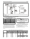
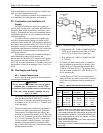
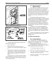
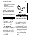
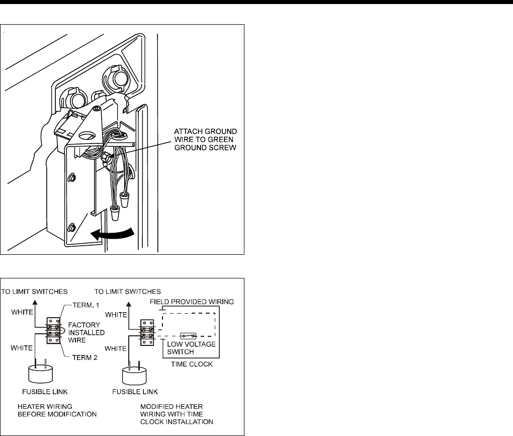
Figure 8. Field Wiring Connections (LD).
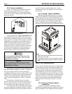
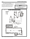
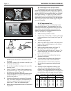
Figure 9. Time Clock Wiring.
To install a time clock auxiliary switch into the
heater wires (see Figure 9):
1. Remove heater door.
2. Remove the factory installed wire between
terminals 1 and 2 on the terminal strip (see Figure
9).
3. Connect the wires from the time clock auxiliary
switch to the two terminals. Use American Wire
Gage (AWG) No. 14 gauge stranded copper wire
with a temperature rating of 221°F (105°C) or
greater.
The length of the wire between the heater and the
time clock should not exceed 10-15 feet (4.57 m). The
contact points of the time clock switch should be silver,
or a low resistance alloy.
2F-3. Remote Operation
(Model LD Only)
The Laars Lite 2 pool/spa heater controls can
be wired for remote operation. The CS-02 remote
control permits switching from one temperature
controller to the other and turning the heater on and
off from a remote location. The CS-04 includes the
same features as the CS-02 plus a remote tempera-
ture controller. Contact Waterpik Laars for further
information. Reference part numbers CS-02 and
CS-04.
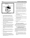
An interrupt (on/off) type remote can be
connected by removing the jumper wire on the terminal
block located in the control compartment (see Figure 6)
and connecting the two wires from the remote to the
two terminals on the terminal block. This type of
remote control will turn the heater on or off, but will
not switch between the two temperature controllers on
the temperature control panel or allow for temperature
adjustments.
To connect a 3-wire remote (not supplied by
Waterpik Laars) to a Laars Lite 2 LD heater, order a
wire harness assembly (part No. E0120000) which
connects to the temperature control panel. Installation
instructions are included with the wire harness assem-
bly.
Consult with Waterpik Laars Service Department
with questions about installing remotes other than
Waterpik Laars.
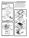
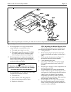
2G. Water Flow System
2G-1. Flange Installation
The heater has 2" NPT universal header cou-
plings. You can connect threaded 2" NPT iron pipe,
unthreaded 1-1/2" iron pipe, 1-1/2" or 2" copper pipe
without an adapter (see Figure 10).
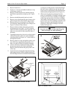
Plastic piping (PVC Schedule 40) can be con-
nected to the heater if local codes allow it, by using the
CPVC nipples included with your heater.
To install plastic piping (see Figure 11):
1. Remove CPVC nipples from plastic bag.
2. Screw CPVC nipples into metal flange until tight,
using teflon tape on plastic threads.
3. Attach PVC plumbing to CPVC pipes using PVC
to CPVC cement only.