


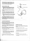

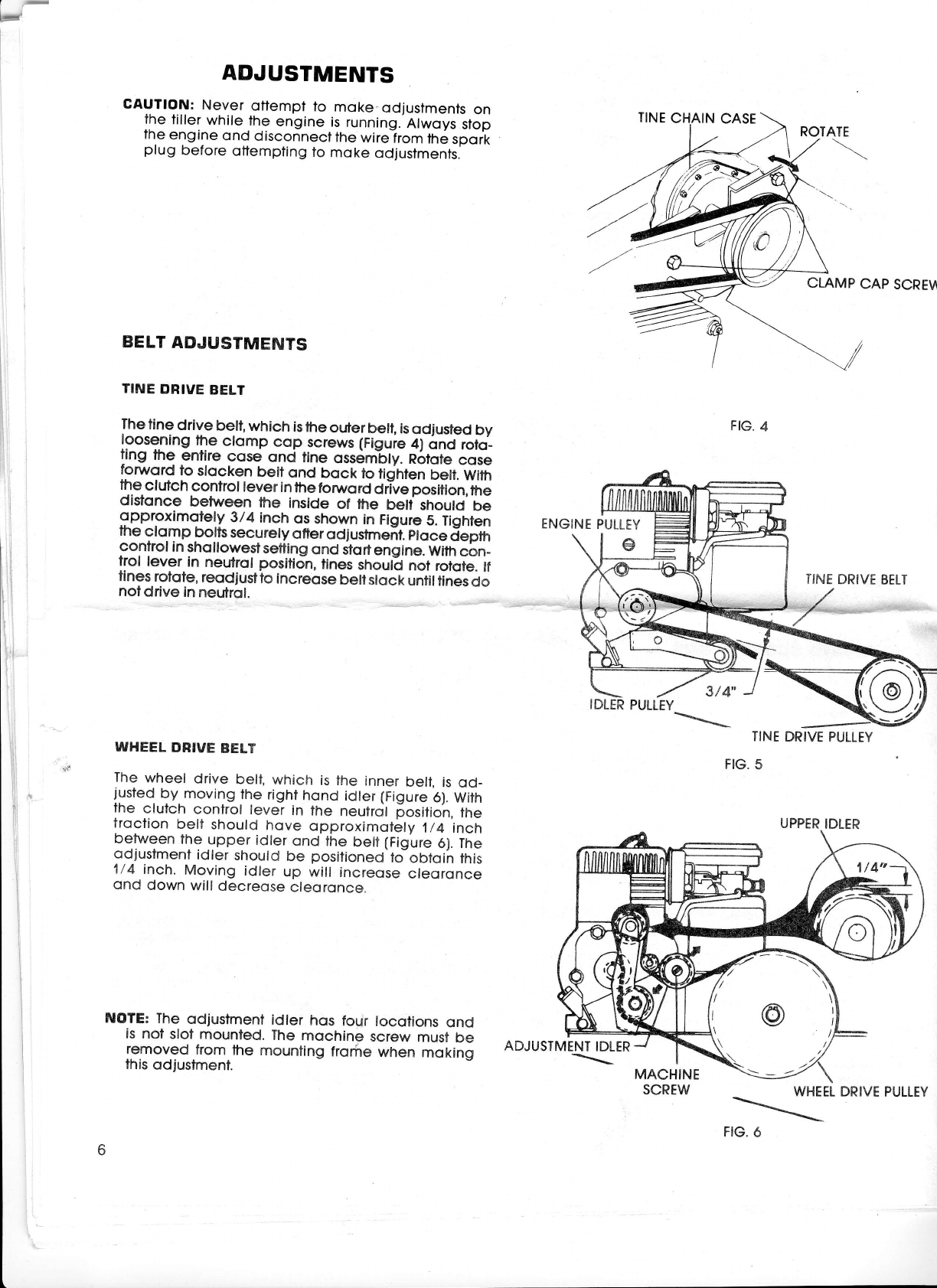
ADJUSTMENTS
CAUTION:
Never
ofiempt
to
moke-odjustments
on
fhe
liller
while
the
engine
is
running.
Alwoys
stop
lhe
engine
ond
disconnecl
the
wirelrom
tn6
spoit
plug
before
ottempling
to
moke
odjustments.
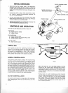
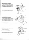
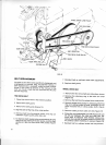
BELT
ADJUSTMENTS
TINE
DBIVE
BELT
The
tine
drive
belt,
which
is
the
outer
be[,
is
odjusted
by
l9_9s9ning
the
ctomp
cop
screws (Figuie
4)
onct
roto_
ang
me
enflre
cose
qnd
tine
ossembly.
R6lote
cose
fonrord
to
stocken
belt
ond
bock
to
fidnten
belt,
With
the
clutch
control
lever
in
the
forword
drlve
position,
the
disfonce
between
the
inside
of fhe
betf
shoutd
be
$Pproximotely
3/4
inch
os
shown
in
Figure
5.
Tighten
the
clo.m
p
bolts
secu
rety
ofter
od
j
ustmeit.
eto
ce
jepm
control
in
shollowestsetting
ond
itortensine.
With
cbn_
trol
lever
in
neutrol
position,
tines
shoult
not
rofote.
lf
flnes
rotote,
reodjustto
increqse
bellslock
untiltines
do
notdrive
in
neutrol.
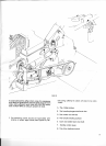
WHEEL
DRIVE
BELT
The
wheel
drive
belt,
which
is the
inner
beli,
is
od_
justed
by. moving
the
right
hond
idter
(Figure
6).
With
the
clutch
confrol
lever
in
the
neutrcjl
[ositioh,
tfre
troclion
belt
should
hove
opproximoiely
1/4
inch
between
the
upper
idler
ond
the
belf
(Figure
6). The
qdiustment
idler
should
be
positioneO-to
oOtqih
this
1/4
inch.
Moving
idler
up will
increose
cteoronce
ond
down
will
decreose
cleoronce.
ENGINE
PULLEY
c
ADJUSTMENT
IDLER
\
TINE
DRIVE
PULLEY
FIG.
5
CLAMP
CAP
SCRE\A
TINE
DRIVE
BELT
FIG.
4
3t4
NOTE:
The
odjustment
idler
hos
four
locotions
ond
is
nol
sloi
mounted.
The
mochine
screw
must
be
removed
from
the
mounting
frorire
when
moking
this
odjustmenl.
MACHINE
SCREW
WHEEL
\
FIG.
6
ROTATE
UPPER
IDLER
DRIVE
PULLEY