


ment
on
which the
engine
is
used,
specifies the top
governed
no load
speed at
which the
engine
may
be
operated. DO NOT EXCEED this speed.
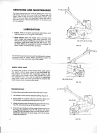
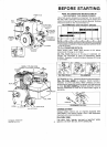
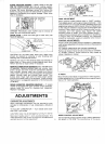
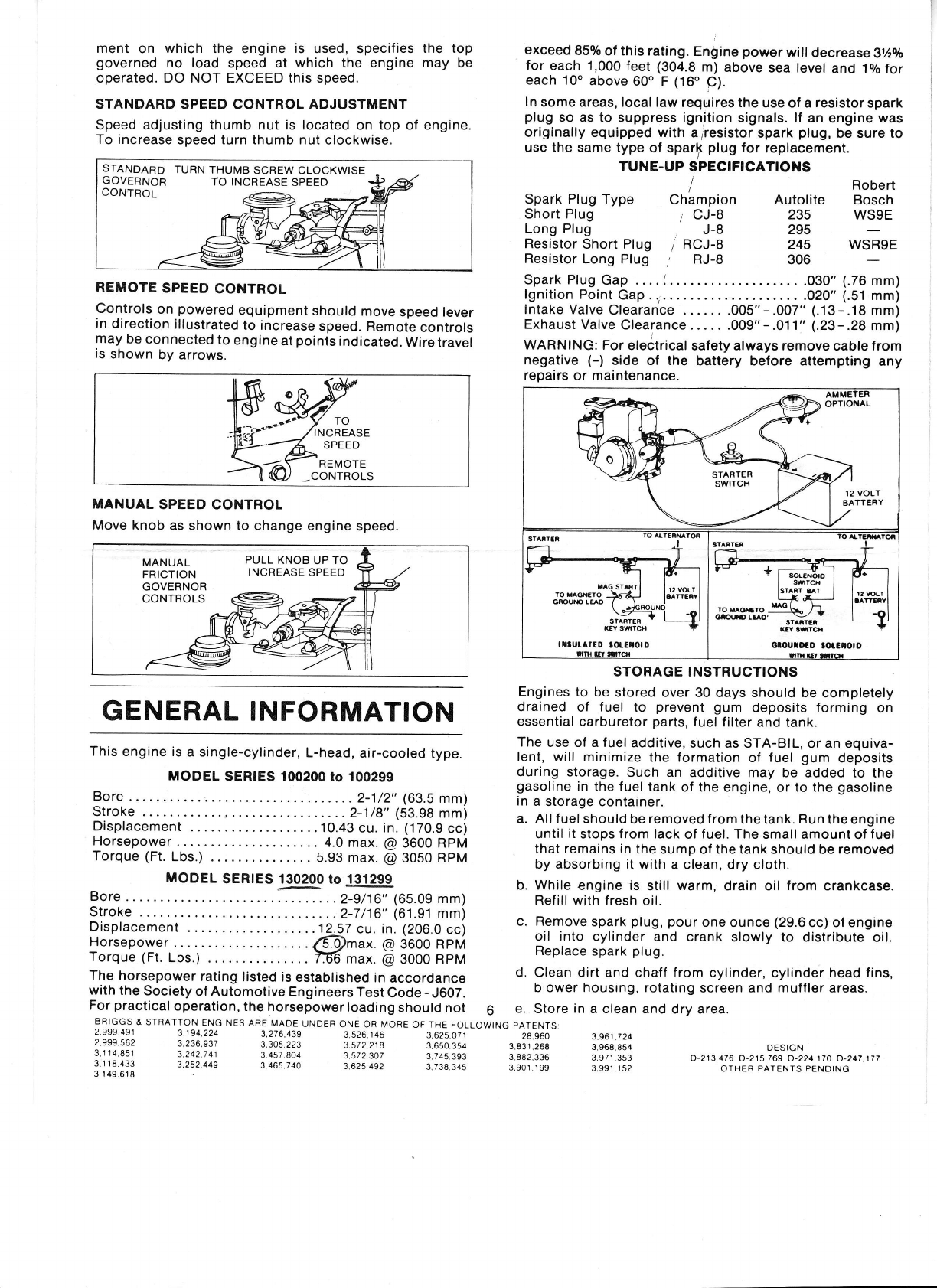
STANDARD
SPEED CONTROL ADJUSTMENT
Speed adjusting thumb nut is located
on
top
of engine.
To increase
speed turn thumb nut
clockwise.
REMOTE
SPEED
CONTROL
Controls
on
powered
equipment
should
move
speed lever
in
direction
illustrated
to increase
speed.
Remote
controls
may
be
connected
to
engine
at
points
indicated.
Wiretravel
is
shown
by arrows.
SPEED
REMOTE
MANUAL
SPEED CONTROL
Move knob
as shown to
change engine
speed.
exceed
85%
of this
rating.
Engine
power
will decrease
3%%
for
each 1,000
feet
(304.8
m)
above
sea level
and
1o/otor
each
10o
above 600 F (16"
C).
ln
some areas, local law
reqtlires the
use of a
resistor
spark
plug
so as
to suppress ignition
signals. lf an
engine
was
originally equipped with
airesistor
spark
plug,
be
sure
to
use the
same type
of sparf
plug
for
replacement.
TUNE.UP
SPECIFICATIONS
Spark
Plug
Type
Chlmpion
Short Plug
i
CJ-8
Long Plug
J-8
Resistor
Short Plug
7
RCJ-8
Resistor
Long Plug
,
RJ-8
Robert
Autolite
Bosch
235
WSgE
295
245 WSRgE
306
This
engine is
a single-cylinder,
L-head,
air-cooled
type.
MODEL
SERIES 100200
to 100299
Bore .
.
. .. 2-1/2"
(63.5
mm)
Stroke
..2-1/8"
(53.98
mm)
Displacement
.....
10.43
cu. in.
(170.9
cc)
Horsepower
4.0
max.
@
3600 RpM
Torque
(Ft.
Lbs.)
. 5.93 max.
@
3050 RPM
MoDEL
SER|ES
l-99ry
ro
:t312ee
Bore..
.2-9/16,,(65.09
mm)
Stroke
.2-7/16"
(61.91
mm)
Displacement.....
12.57cu.
in.(206.0cc)
Horsepower
......
$@nax.
p
iooo neM
Torque (Ft.
Lbs.)
. 155 max.
E
aOOO neU
The horsepower
rating
listed is
established
in
accordance
with
the
Society
of
Automotive
Engineers
Test
Code
-
J607.
For
practical
operation,
the horsepower
loading
should
not
6
ERIGGS
& STRATTON
ENGINES
ARE MADE
UNDER
ONE OR MORE
OF THE FOLLOWING
PATENIS
2.999.491
3.194.224
3,276,439
3.526.146
3,625,071
28.960
2.999,562
3.236,937
3,305 223
9.572.218
3,650,354
3.831.26E
Spark Plug
Gap . . .. | . ..
. . .030"
(.76
mm)
fgnition Point
Gap ..r.....
. .02O"
(.51
mm)
fntake Valve
Clearance
...... .005"-.OO7"
(.13-.18
mm)
Exhaust Valve
Clearance
. . . . . .009"
-
.01 1"
(.23
-.28
mm)
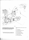
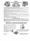
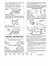
WARNING: For
eleitrical
safety always
remove
cable from
negative
(-)
side of the
battery before attempting
any
repairs
or
maintenance.
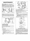
Engines
to be
stored
over 30 days should
be completely
drained
of
fuel
to
prevent
gum
deposits forming
on
essential
carburetor
parts,
f
uel f ilter and
tank.
The
use ol a f
uel additive,
such as STA-BlL,
or
an
equiva-
lent,
will minimize
the formation
of fuel
gum
deposits
during storage.
Such an
additive may be
added to the
gasoline
in the fuel
tank
of the engine,
or
to the
gasoline
in
a storage
container.
a. All f
uel should
be
removed f rom
the tank.
Run
the engine
until
it
stoos from lack
of
f
uel.
The
small amount of
fuel
that remains
in
the sumo
ol
the tank
should be
removed
by absorbing it with
a clean, dry
cloth.
b. While
engine is
still
warm,
drain oil
from
crankcase.
Refill with fresh
oil.
c. Remove
spark
plug,
pour
one ounce
(29.6
cc) of engine
oil into
cylinder
and crank
slowly to distribute
oil.
Replace
spark
plug
d. Clean dirt and
chaff
from
cylinder,
cylinder
head fins,
blower housing, rotating
screen
and muffler areas.
e.
Store
in
a clean
and dry area.
GENERAL
INFORMATION
3114851
3.1
1
8.433
3 149 618
3.242.7 41
3.252.449
3,457.804
3.465.740
3,572
307
3.625,492
3 745.393
3,738.345
3 882,336
3,90r.1 99
3,961
724
3 968,854
3,97
1
,353
3,991
,1
52
D€SIGN
D-213,475 D-215,769
0-224.170 0-247.177
OTHER
PATENTS PENDING
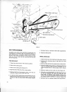
STANDARD
TURN THUMB
SCREW CLOCKWISE
GOVERNOR
TO INCREASE
SPEED
MANUAL
PULL
KNOB UP TO
FR1CT;ON
INCREASE
SPEED
GOVERNOR
12 VOLT
BATTERY
IITUL TED
IOLETOID
rouo[ro
____:l\
/
,
oa(xrc !ao.
"rxr..
STORAGE INSTRUCTIONS