


Assembly Instructions
20
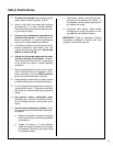
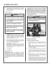
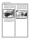
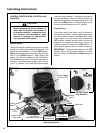
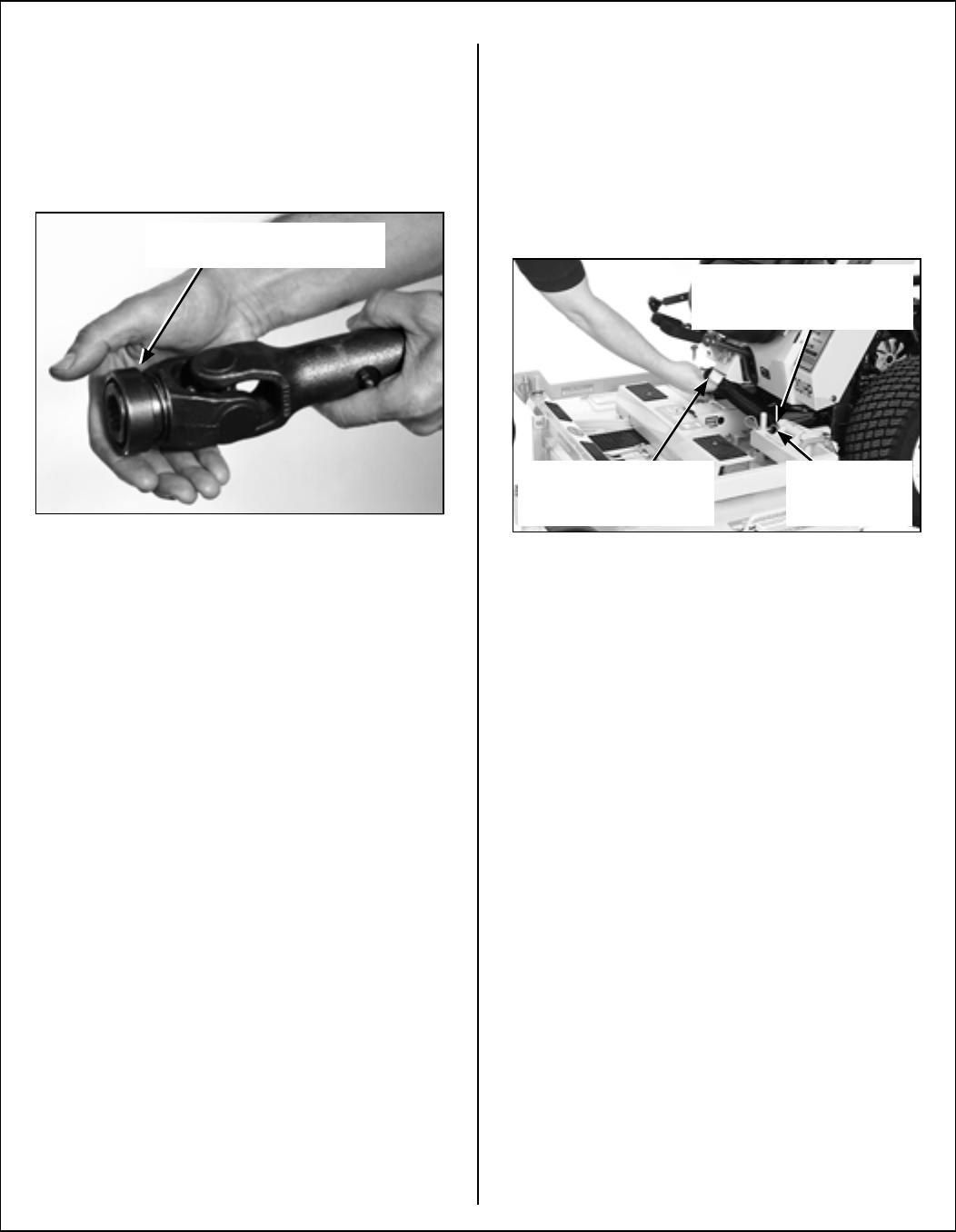
IMPORTANT: To prevent damage to the
mower, make sure the PTO shaft assembly is
securely locked on the tractor, with the locking
balls fully seated in the groove and the ring in the
full forward position (refer to the Coupler Ring
“Locked” Position photo). After installation,
pull on the shaft to check for security.
Coupler Ring “Locked” Position
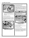
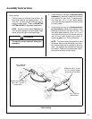
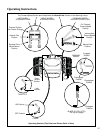
8. Raise the mower body (instead of lifting the
front of deck) and clip the counterweight springs
to the receptacle on front of body. Lower the
body to tension the springs. (Refer to Deck
Counterweight Spring Installation Photo.)
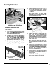
9. With the counterweight springs connected, the
weight on the deck caster wheels should be
15 to 25 Ib (6.8 to 11.3 kg). Check this weight
by lifting on the front of the deck carrier frame. If
required, the spring tension can be adjusted by
tightening or loosening the elastic stop nuts
located underneath the lower spring hook.
Refer to Deck Counterweight Spring Installa-
tion photo.
Deck Counterweight Spring Installation
Spring-Loaded Coupler Ring
In Fully Forward Position
Hitch Pins
Lock Deck On
Support Arms
Spring Tension Adjustment
Nut Located Under Lower
Spring Hook (Not Visible)
Counterweight Springs
Clip Onto Body
With Body Tilted Up