


24 se c t i O n 6— Ma i n t e n a n c e & ad j u s t M e n t s
Adjustments
Adjusting the Seat
See the Assembly & Set-Up section for information on adjusting seat.
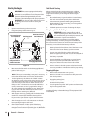
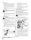
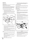
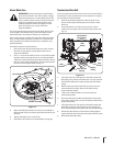
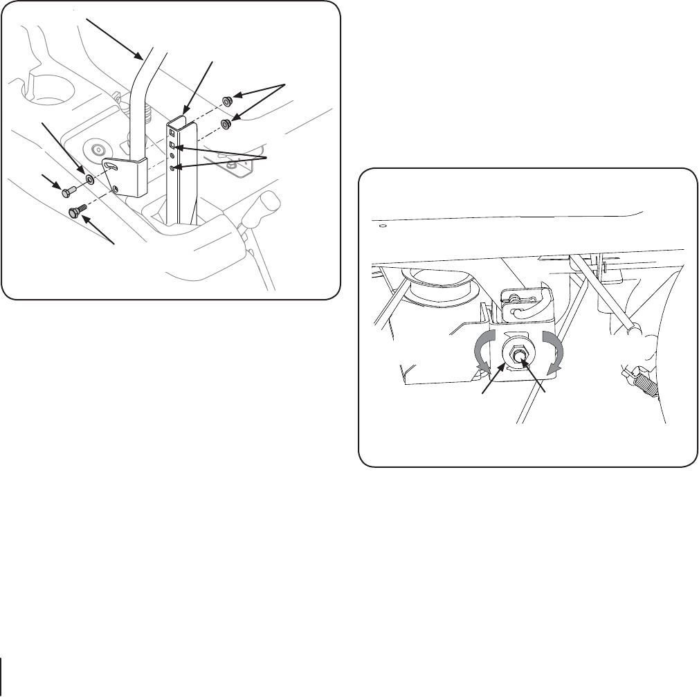
Adjusting RH & LH Drive Control Levers
and fore-and-aft for the comfort of the operator. The drive
control levers can be placed in either of two height positions,
and/or can be moved forward or rearward within the range of
the slot in each control lever mounting bracket.
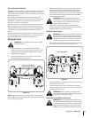
To adjust the drive control lever height, proceed as follows:
Remove the flange lock nut, flat washer, and hex screw
securing the lever to the pivot bracket.
While supporting the control lever to keep it from falling, 2.
remove the hex insert flange lock nut and shoulder screw
from the bottom of the control lever and pivot bracket.
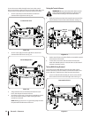
Reposition the control lever to align with the other set of 3.
holes in the pivot bracket and insert the shoulder screw
removed earlier. Fasten with the hex insert flange lock nut
and tighten until snug.
Insert the hex screw with washer through the control lever
slot and the pivot bracket. Thread the flange lock nut onto
the screw, but do not tighten now.
If you are going to adjust the control levers forward or rearward, 5.
proceed to the next step. If not, fully tighten the flange lock nut.
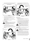
To adjust the drive control levers forward or rearward, proceed as
follows:
If not already loose, loosen the flange lock nut and rotate
the control lever either forward or rearward to the desired
NOTE: If the control lever is too tight to move, slightly
loosen the hex insert flange lock nut and shoulder screw at
the bottom of the control lever.
Tighten the flange lock nut to fix the control lever in the 2.
adjusted position.
Repeat the above procedure to adjust the other control 3.
lever into the same position. Adjust so that both levers are
even with each other when in the neutral position.
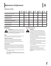
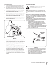
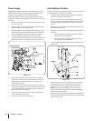
Leveling the Mower Deck
When correctly adjusted the mower deck should be level side to
side, and the front of the deck should be approximately ⁄
than the rear of deck.
NOTE:
deck leveling adjustments. See the tire side wall for proper
inflation pressures.
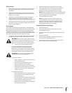
If the cutting deck appears to be mowing unevenly, a side
to side adjustment can be performed. Adjust if necessary
as follows:
With the tractor parked on a firm, level surface, place the 2.
deck lift handle in the top notch (highest position) and
rotate both outer blades so that they are perpendicular to
the tractor frame.
Lower the deck to the middle height position.3.
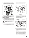
Measure the distance from the outside left blade tip to the
ground and the distance from the outside right blade tip to
not, proceed to the next step.
Comparing the two measurements, determine whether the 5.
left side of the deck must be raised or lowered.
Loosen, but do not remove, the hex cap screw on the left
Level the deck by using a wrench to turn the adjustment gear 7.
(found immediately behind the hex cap screw just loosened)
clockwise to raise the left side of the deck, or counterclockwise
The deck is properly leveled when left and right blade tip 8.
measurements are equal.
Retighten the hex cap screw on the left deck hanger
bracket when proper adjustment is achieved.
Raise Left