


10 se c t i O n 2— as s e M b l y & se t-up
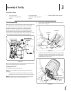
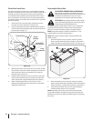
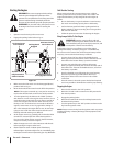
Position Drive Control levers
The drive control levers of the tractor are lowered for shipping
purposes. The flange lock nuts, hex screws, and flat washers that
normally secure the control levers in their operating position
are unfastened and installed in the slotted holes of the control
levers for shipment. The control levers must be repositioned to
operate the tractor. To reposition the control levers for operation,
proceed as follows:
Remove the hex screw, flat washer, and flange lock nut
from the slot of one of the drive control levers.
Lift and swing that control lever upward until the slotted 2.
hole in the lever bracket aligns with one of the holes in the
Slide the flat washer onto the hex screw. From the outside, 3.
insert the hex screw with washer through the control lever
slot and the hole of the pivot bracket. Secure with the
Note the relative position of the control lever to the pivot
bracket, then repeat the previous steps to reposition the
other control lever in approximately the same position.
5.
Maintenance & Adjustments for instructions on the final
adjustment of the levers.
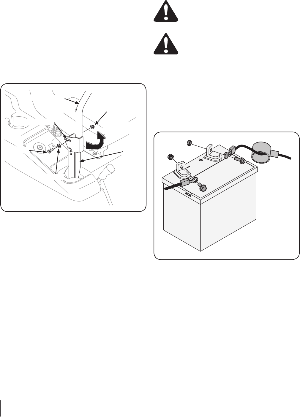
Bracket
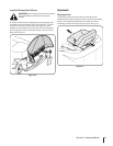
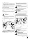
Connecting the Battery Cables
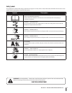
!
Battery posts, terminals, and related accessories
contain lead and lead compounds, chemicals known
to the State of California to cause cancer and
reproductive harm. Wash hands after handling.
When attaching battery cables, always
followed by the NEGATIVE (Black) wire.
For shipping reasons, both battery cables on your equipment
may have been left disconnected from the terminals at the
factory. To connect the battery cables, proceed as follows:
NOTE:
negative battery terminal is marked Neg. (–).
NOTE: If the positive battery cable is already attached, skip
ahead to step 2.
Remove the plastic cover, if present, from the positive
battery terminal and attach the red cable to the positive
Remove the plastic cover, if present, from the negative 2.
battery terminal and attach the black cable to the negative
battery terminal (–) with the bolt and hex nut. See Fig. 3-5.
3.
terminal to help protect it from corrosion.
NOTE: If the battery is put into service after the date shown
on top/side of battery, charge the battery as instructed in the
the tractor.