


5
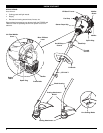
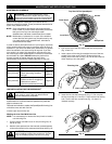
INSTALLING AND ADJUSTING THE D-HANDLE
Install
1. Remove the screws and bottom clamp piece that were
installed on the D-handle for shipping.
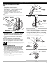
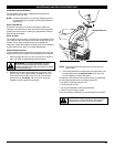
2. Place D-handle the over the shaft housing and onto the
bottom clamp (Fig. 1). Place it a minimum of 6 inches
(15.24 cm) from the end of the shaft grip.
3. Start screws with a large Flat-head or T-25 Torx
screwdriver. Do not tighten until you make the handle
adjustment.
Adjust
4. If the D-handle was pre-installed, loosen the screws on the
handle just enough to move it.
(4) Screws
Shaft
Housing
D-Handle
Bottom Clamp
Shaft Grip
Minimum 6 inches
(15.24 cm)
On/Off Stop Control
5. While holding the unit in the operating position, manuever
the D-handle to the location that provides you the best
grip.
6. Tighten the clamp screws evenly, until the D-handle is
secure.
Fig. 1
INSTALLING THE CUTTING ATTACHMENT SHIELD
Use the following instructions if the cutting attachment shield
on your unit is not installed or if you ever need to re-install it.
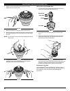
Install on a Straight Shaft (TB75SS)
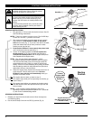
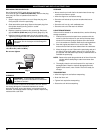
1. Slide the cutting attachment shield into the shield mount
on the cutting attachment. Align the screw holes in the
shield with the holes in the cutting attachment (Fig. 2).
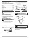
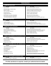
2. Place a hex lock nut into one of the three recessed holes on
the top of the cutting attachment shield (Fig 3).
3. Install a screw into the hole from the bottom of the cutting
attachment shield and screw it into the nut installed in step
2 (Fig 3). Do not tighten.
4. Repeat steps 2 and 3 until all three screws have been
started, then tighten securely.
Fig. 2
Fig. 3
Screws (3)
Shaft Housing
Hex Lock Nut
Cutting
Attachment
Shield
Cutting Attachment
Recessed
Holes
Shield Mount
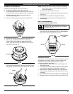
Install on a Curved Shaft (TB25CS)
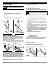
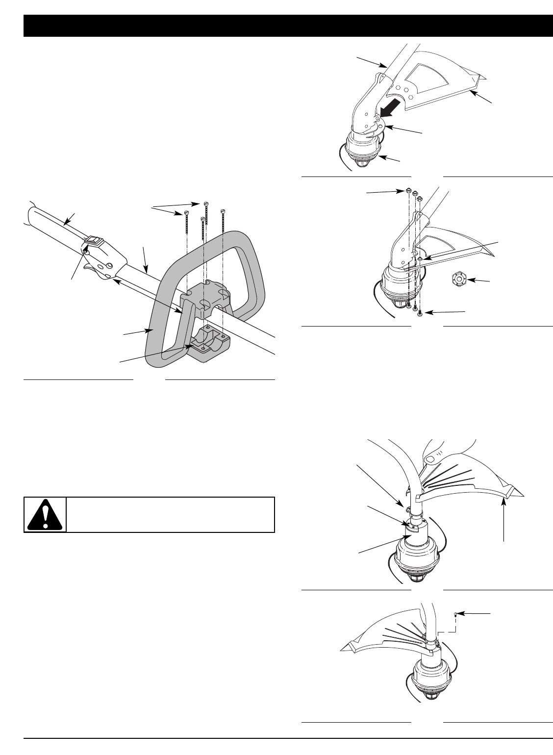
1. Place the cutting attachment shield onto the shaft housing
above the clamp assembly (Fig. 4).
2. Push the cutting attachment shield down to the top of the
cutting attachment assembly and then rotate the cutting
attachment shield until the screw holes align and the guard
fits into the recessed pocket (Fig. 4).
3. Install the screws with a Phillips screwdriver (Fig. 5).
Fig. 4
(4) Screws
Clamp
Assembly
Cutting
Attachment
Assembly
Cutting
Attachment Shield
Recessed
Pocket
Fig. 5
ASSEMBLY INSTRUCTIONS
WARNING: Never operate the trimmer without
the cutting attachment shield in place to prevent
serious personal injury.
Nuts (3)