


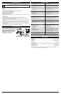
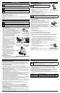


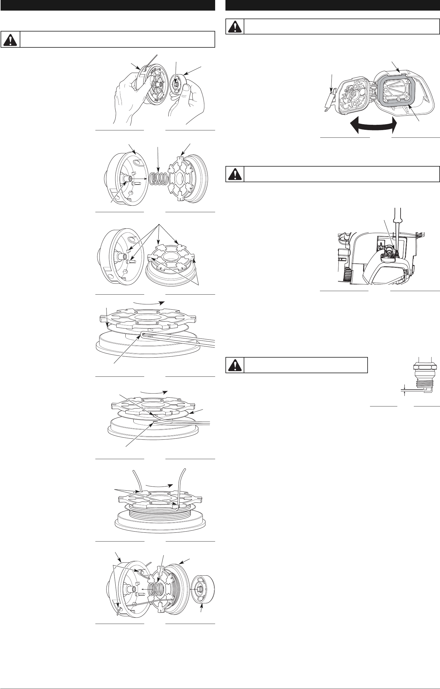
MAINTAINING THE SPARK PLUG
1. Stop the engine and allow it to cool. Grasp the spark plug boot firmly and pull it from the spark plug.
2. Clean around the spark plug. Remove the spark plug from the cylinder head with a 5/8-inch
socket, turning counterclockwise.
3. Inspect the spark plug. If the spark plug is cracked, fouled or
dirty, replace it with a replacement part #753-06193, a
Champion RDJ7J or an equivalent spark plug.
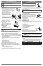
4. Use a feeler gauge to set the air gap at 0.025 in. (0.635 mm)
(Fig. 22).
5. Install the spark plug in the cylinder head. Tighten the spark
plug with a 5/8-inch socket, turning it clockwise until snug.
NOTE: If using a torque wrench, torque to:
110-120 in.•lb. (12.3-13.5 N•m). Do not over tighten.
6. Reattach the spark plug boot.
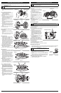
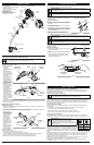
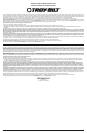
REPLACING THE TRIMMING LINE
Only use the trimming line described in the Specifications section. Other types of trimming line may
cause the engine to overheat or fail.
NOTE: Always use the corr
ect line length
when installing trimming line. The line
may not release properly if the line is too
long.
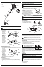
Part 1 - Removing the Inner Reel
1. Hold the outer spool with one hand and
unscrew the bump knob
counterclockwise (Fig. 13).
NOTE: The outer spool will remain attached
to the unit.
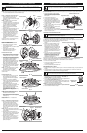
2. Inspect the bolt inside the bump knob to
make sure it moves freely. Replace the
bump knob if it is damaged.
3. Remove the inner reel from the outer
spool (Fig. 14).
4. Remove the spring from the inner reel
(Fig. 14).
5. Use a clean cloth to clean the inner reel,
spring, shaft and inner surface of the
outer spool.
6. Check the indexing teeth and holding slots
for wear (Fig. 15). If necessary
, remove
burrs or replace the inner reel and outer
spool.
Proceed to Part 2 - Winding New Trimming
Line onto the Inner Reel.
Part 2 - Winding New Trimming Line onto
the Inner Reel
• If using single line, refer to Winding
Single Line.
• If using split line, refer to Winding Split
Line.
• If using a prewound inner reel, proceed to
Part 3 - Installing the Inner Reel.
Winding Single Line
1. Cut one 12-foot (3.7 m) length of new
single trimming line. Fold the line in half
to create a loop in the middle.
2. Insert the loop into the slot in the split
wall (Fig. 16). Wind the line tightly in the
direction shown on the bottom of the
inner reel until about 6 inches (150 mm)
of line remains. Keep the top half of the
line above the split wall and the bottom
half of the line below the split wall.
3. Insert the two 6-inch sections into the
two .095 holding slots (Fig. 18).
NOTE: Failure to wind the line in the
direction indicated will cause the cutting
head to operate incorrectly.
Proceed to Part 3 - Installing the Inner Reel.
Winding Split Line
1. Cut one 6-foot (1.8 m) length of new split
line trimming line. Split each end about 6
inches (150 mm).
2. Using one split end, insert one line into
the top hole and the other line into the
bottom hole in the inner r
eel (Fig. 17).
3. Wind the line tightly in the direction
shown on the bottom of the inner reel.
The split wall will automatically divide the
line. Wind the line until it is completely
divided and about 6 inches (150 mm) of
line remains.
NOTE: Failure to wind the line in the
direction indicated will cause the cutting
head to operate incorrectly.
4. Insert the two 6-inch sections into the
two .095 holding slots (Fig. 18).
Proceed to Part 3 - Installing the Inner Reel.
Part 3 - Installing the Inner Reel
1. Pass the two line ends through the
eyelets in the outer spool. Place the
spring inside the inner reel. Insert the
inner reel into the outer spool. Push the
inner reel and outer spool together (Fig.
19).
NOTE: The spring must be assembled on
the inner reel before reassembling the
cutting head.
2. While holding the inner reel and outer
spool together, firmly pull the two line
ends to release them from the holding
slots.
3. While holding the inner reel and outer
spool together, screw the bump knob on
clockwise. Tighten the bump knob
secur
ely.
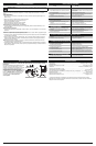
AIR FILTER MAINTENANCE
Cleaning the Air Filter
Failure to maintain the air filter properly can result in poor performance or can cause permanent damage
to the engine.
1. Open the air filter cover by pressing the
lock tab in and pulling out on the air filter
cover (Fig. 20).
2. Remove the air filter (Fig. 20).
3. Wash the filter in detergent and water.
Rinse the filter thoroughly and allow it to
dry.
4. Apply enough clean SAE 30 motor oil to
lightly coat the filter.
5. Squeeze the filter to spread and remove
excess oil.
6. Replace the air filter into the air filter cover
(Fig. 20).
NOTE: Operating the unit without the air filter
WILL VOID the warranty.
7. Close the air filter cover by swinging it to the left and then pressing it down until the lock tab snaps into
place (Fig. 20).
5
WARNING:
To avoid serious personal injury, always turn the unit off and allow it to cool
before you clean or service it.
Fig. 20
Air Filter Cover
Air Filter
Lock Tab
MAINTENANCE AND REPAIR INSTRUCTIONSMAINTENANCE AND REPAIR INSTRUCTIONS
WARNING:
Never use metal-reinforced line, wire, chain or rope. These can break off and
become dangerous projectiles.
Fig. 13
Bolt
Bump Knob
Outer Spool
Fig. 14
Outer Spool
Spring
Inner Reel
Shaft
Fig. 15
Indexing Teeth
Holding Slots
Fig. 16
Slot
Split Wall
Fig. 17
Top Hole
Bottom Hole
Split
Wall
Fig. 18
Holding
Slots
Fig. 19
Outer Spool
Bump Knob
Inner Reel
Spring
Eyelets
IDLE SPEED ADJUSTMENT
NOTE: Careless adjustments can seriously damage the unit. An authorized service dealer should make
carburetor adjustments.
If, after checking the fuel mixture and cleaning the air filter, the engine still will not idle, adjust the idle
speed screw as follows:
1. Start the engine and run for one minute to
warm up. Refer to Starting and Stopping
Instructions.
2. Release the throttle trigger and let the
engine idle. If the engine stops, insert a
small Phillips screwdriver into the idle
adjustment screw (Fig. 21). Turn the idle
speed screw clockwise 1/8 of a turn at a
time (as needed) until the engine idles
smoothly.
3. If the engine appears to be idling too fast,
turn the idle speed screw
counterclockwise 1/8 of a turn at a time
(as needed), to r
educe idle speed.
Checking the fuel mixture, cleaning the air
filter and adjusting the idle speed should
solve most engine problems. If not and all of
the following are true:
• the engine will not idle
• the engine hesitates or stalls on acceleration
• there is a loss of engine power
Have the carburetor adjusted by an authorized service dealer.
Fig. 21
Idle Adjustment Screw
WARNING:
Do not sand blast, scrape or clean
electrodes. Grit in the engine could damage the cylinder.
WARNING:
The cutting attachment will spin during idle speed adjustments. Wear
protective clothing and observe all safety instructions to prevent serious personal injury.
Fig. 22
0.025 in.
(0.635 mm.)