


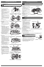
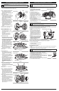


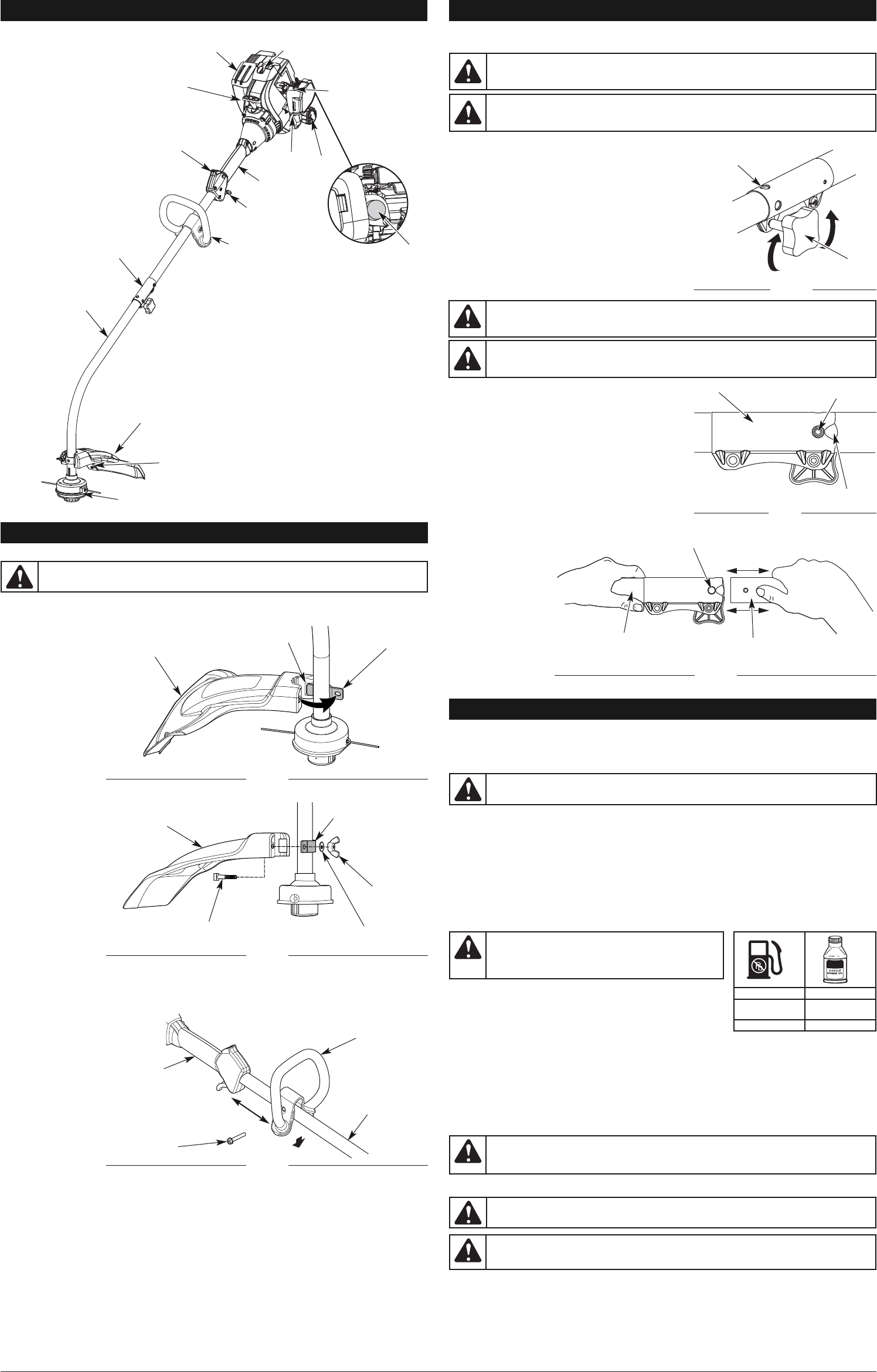
INSTALLING THE CUTTING HEAD SHIELD
Use the following instructions if the cutting head shield is not installed. Use only the instructions that
apply to the type of shaft and shield equipped with this unit.
1. Remove the wing nut
and washer from the
cutting head shield.
2. Insert the short tab
(the one without a
hole) on the mount
bracket into the slot
on the cutting head
shield (Fig. 1).
3. Rotate the cutting
head shield
counterclockwise to
align the hole on the
cutting head shield
with the hole on the
mount bracket (Fig. 1).
4. Insert the square bolt into the hole underneath the cutting head shield (Fig. 2). Push the square bolt
through the cutting
head shield and
mount bracket.
5. Put the washer onto
the square bolt (Fig. 2).
6. Screw the wing nut
onto the square bolt
until the cutting head
shield is firmly in
place (Fig. 2).
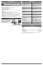
OPERA
TING THE COUPLER
The coupler enables the use of various optional attachments.
NOTE: To make installing or removing the attachment
easier, place the unit on the ground or on a work bench.
Installing the Attachment
NOTE: Remove the protective cap and gray spacer from
the upper and lower shafts prior to assembling the
attachment.
1. Turn the knob counterclockwise to loosen (Fig. 4).
2. While firmly holding the attachment, push it straight
into the coupler until the release button snaps firmly
into the primary hole (Fig. 6).
NOTE: Aligning the release button with the guide recess
will help installation (Fig. 5).
3. Turn the knob clockwise to tighten (Fig. 4).
For decorative edging with a string trimmer attachment,
lock the release button into the 90° edging hole (Fig. 4).
Removing the Attachment
1. Turn the knob counterclockwise to loosen (Fig. 4).
2. Press and hold the release button (Fig. 5).
3.
While firmly holding the upper shaft housing, pull the
attachment straight out of the coupler (Fig. 6).
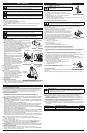
OIL AND FUEL MIXING INSTRUCTIONS
Old and/or improperly mixed fuel are the main reasons for the unit not running properly. Be sure to use
fresh, clean unleaded fuel. Follow the instructions carefully for the proper fuel/oil mixture.
DEFINITION OF BLENDED FUELS
Today's fuels are often a blend of gasoline and oxygenates such as ethanol, methanol, or MTBE (ether).
Alcohol-blended fuel absorbs water. As little as 1% water in the fuel can make fuel and oil separate. It
forms acids when stored. When using alcohol-blended fuel, use fresh fuel (less than 30 days old).
USING BLENDED FUELS
If choosing to use a blended fuel, or its use is unavoidable, follow recommended precautions:
• Always use the fresh fuel mix explained in the operator's manual
•Use the fuel additive STA-BIL® or an equivalent
• Always agitate the fuel mix before fueling the unit
• Drain the tank and run the engine dry before storing the unit
USING FUEL ADDITIVES
The bottle of 2-cycle oil contains a fuel additive which will help inhibit
corrosion and minimize the formation of gum deposits. It is
recommended to use our 2-cycle oil with this unit.
If unavailable, use a good 2-cycle oil designed for air-cooled engines
along with a fuel additive, such as STA-BIL Gas Stabilizer or an
equivalent. Add 0.8 oz. (23 ml) of fuel additive per gallon of fuel
according to the instructions on the container. NEVER add fuel additives directly to the unit’s fuel tank.
Thoroughly mix the proper ratio of 2-cycle engine oil with unleaded fuel in a separate fuel can. Use a
40:1 fuel/oil ratio. Do not mix them directly in the engine fuel tank. See the table for specific gas and oil
mixing ratios.
NOTE:
One gallon (3.8 liters) of unleaded fuel mixed with one 3.2 oz. (95 ml) bottle of 2-cycle oil makes a 40:1
fuel/oil ratio.
NOTE: Dispose of the old fuel/oil mix in accordance to federal, state and local regulations.
FUELING THE UNIT
1. Turn unit on its side, with the fuel cap facing up, and remove the fuel cap.
2. Place the gas container’s spout into the fill hole on the fuel tank and fill the tank.
NOTE: Do not overfill the tank.
3. Wipe up any gasoline that may have spilled.
4. Reinstall the fuel cap.
5. Move the unit at least 30 ft. (9.1 m) from the fueling source and site before starting the engine.
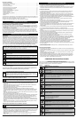
MIXING RATIO - 40:1
3
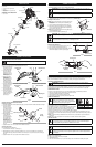
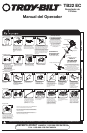
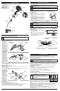
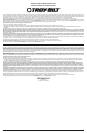
KNOW YOUR UNIT
APPLICATIONS
As a trimmer:
• Cutting grass and light weeds.
• Edging
• Decorative trimming around trees,
fences, etc.
Throttle Control
D-Handle
Shaft Grip
Air Filter
Cover
Spark Plug
Shaft Housing
Starter Rope Grip
Line Cutting
Blade
Muffler
On/Off Control
Cutting Head
Cutting Head Shield
Fuel Cap
OIL AND FUEL INFORMATION
ASSEMBLY INSTRUCTIONS
WARNING:
To prevent serious personal injury, never operate the trimmer without the
cutting attachment shield in place.
Choke Lever
Primer Bulb
UNLEADED GAS 2 CYCLE OIL
1 GALLON US
(3.8 LITERS)
3.2 FL. OZ.
(95 ml)
1 LITER 25 ml
CAUTION:
For proper engine operation and maximum
reliability, pay strict attention to the oil and fuel mixing
instructions on the 2-cycle oil container. Using improperly
mixed fuel can severely damage the engine.
WARNING:
Gasoline is extremely flammable. Ignited vapors may explode. Always stop
the engine and allow it to cool before filling the fuel tank. Do not smoke while filling the
tank. Keep sparks and open flames at a distance from the area.
WARNING:
Remove fuel cap slowly to avoid injury from fuel spray. Never operate the
unit without the fuel cap securely in place.
WARNING:
Add fuel in a clean, level and well ventilated outdoor area. Wipe up any spilled fuel
immediately. Avoid creating a source of ignition for spilled fuel. Do not start the engine until fuel
vapors dissipate.
WARNING:
It has been proven that fuel containing greater than 10% ethanol will likely
damage this engine and void the warranty.
Coupler
ASSEMBLY TOOLS REQUIRED:
• 3/8” Socket
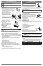
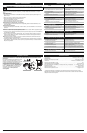
INSTALLING AND ADJUSTING THE HANDLE
Installing the Handle
1. Push the handle down onto the shaft housing (Fig. 3). The bolt hole in the handle should be to the right.
2. Insert the bolt into
the bolt hole and
push it through (Fig.
3). Tighten the bolt
with a 3/ 8” socket,
but do not tighten the
bolt completely .
3. While holding the unit
in the operating
position (Fig. 10),
move the handle to
the location that
provides the best
grip. Place it a
minimum of 6 inches
(15.24 cm) from the
end of the shaft grip
(Fig. 3).
4. Tighten the bolt with a 3/ 8” socket until the handle is secure.
Adjusting the Handle
If the handle requires adjustment:
1. Loosen the bolt with a 3/ 8” socket (Fig. 3).
2. While holding the unit in the operating position (Fig. 10), move the handle to the location that
provides the best grip. Place it a minimum of 6 inches (15.24 cm) from the end of the shaft grip
(Fig. 3).
3. Tighten the bolt with a 3/ 8” socket until the handle is secur
e.
Fig. 3
Bolt
Shaft Grip
Minimum 6 in.
(15.24 cm)
Handle
Shaft
Housing
Fig. 5
Fig. 6
Fig. 4
Release Button
Guide Recess
90˚ Edging Hole
(Trimmer Only)
Knob
Primary Hole
Lower Shaft
Housing
Upper Shaft
Housing
WARNING:
Before using any attachment, read and understand the manual that came
with the attachment. Follow all safety information contained within.
CAUTION:
Before operating the unit, make sure the release button is fully snapped
into the primary hole (Fig. 6) and the knob (Fig. 4) is securely tightened.
WARNING:
To avoid serious personal injury and damage to the unit, shut the unit off
before removing or installing an attachment.
CAUTION:
The release button should be snapped into the primary hole only. Using the
wrong hole could lead to personal injury or damage to the unit.
Coupler
ASSEMBLY INSTRUCTIONS
Fig. 1
Mount Bracket
Cutting Head
Shield
Fig. 2
Washer
Square Bolt
Slot
Wing Nut
Cutting Head
Shield
Mount Bracket