


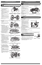
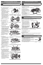


HOLDING THE UNIT
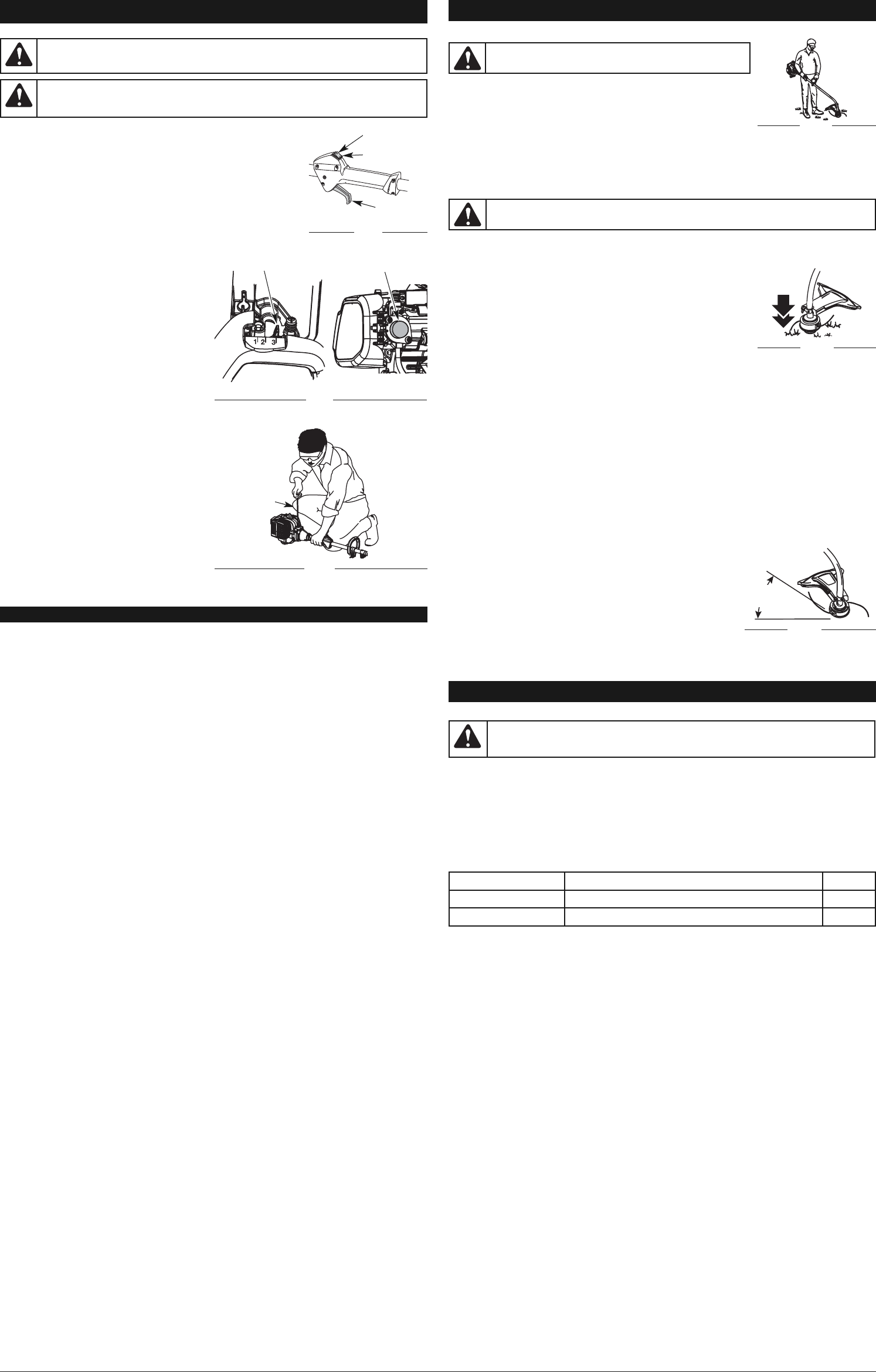
Before operating the unit, stand in the operating position (Fig. 10). Check
for the following:
• The operator is wearing eye protection and proper clothing
• With a slightly-bent right arm, the operator’s hand is holding the shaft
grip
• The operator’s left arm is straight, the left hand holding the D-handle
• The unit is at waist level
• The cutting head is parallel to the ground and easily contacts the grass without the need to bend
over
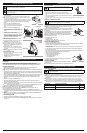
ADJUSTING TRIMMING LINE LENGTH
The Bump Head™ cutting head allows the release of trimming line without stopping the engine. To release more
line, lightly tap the cutting head on the ground (Fig. 11) while operating the unit at high speed.
NOTE:
Always keep the trimming line fully extended. Line release becomes more
difficult when the cutting line gets shorter.
Each time the head is bumped, about 1 inch (25.4 mm) of trimming line releases. A
blade in the cutting head shield will cut the line to the proper length if any excess
line is released.
For best results, tap the bump knob on bare ground or hard soil. If attempting a line
release in tall grass, the engine may stall. Always keep the trimming line fully
extended. Line release becomes more difficult when the cutting line gets shorter.
NOTE: Do not rest the Bump Head™ on the ground while the unit is running.
Some line breakage will occur from:
• Entanglement with foreign matter
• Normal line fatigue
• Attempting to cut thick, stalky weeds
• Forcing the line into objects such as walls or fence posts
TIPS FOR BEST TRIMMING RESULTS
• Keep the cutting head parallel to the ground.
• Do not force the cutting head. Allow the tip of the line to do the cutting, especially along walls. Cutting with more
than the tip will reduce cutting efficiency and may overload the engine.
• Cut grass over 8 inches (200 mm) by working from top to bottom in small increments to avoid premature line
wear or engine drag.
• Cut from right to left whenever possible. Cutting to the left improves the unit's cutting efficiency. Clippings are
thrown away from the operator.
• Slowly move the unit into and out of the cutting area at the desired height. Move either in a forward-backward or
side-to-side motion. Cutting shorter lengths produces the best results.
• Trim only when grass and weeds are dry.
• The life of the cutting line is dependent upon:
• Following the trimming techniques
• What vegetation is being cut
• Where vegetation is cut
For example, the line will wear faster when trimming against a foundation wall
as opposed to trimming around a tree.
DECORATIVE TRIMMING
Decorative trimming is accomplished by removing all vegetation around trees,
posts, fences, etc..
Rotate the whole unit so that the cutting head is at a 30° angle to the ground (Fig. 12).
4
30°
Fig. 12
Fig. 11
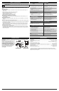
MAINTENANCE SCHEDULE
Perform these required maintenance procedures at the frequency stated in the table. These procedures
should also be a part of any seasonal tune-up.
NOTE: Some maintenance procedures may require special tools or skills. If you are unsure about these
procedures, take your unit to any non-road engine repair establishment, individual or authorized
service dealer.
NOTE: Maintenance, replacement, or repair of the emission control devices and system may be
performed by any non-road engine repair establishment, individual or authorized service dealer.
NOTE: Please read the California/EPA statement that came with the unit for a complete listing of terms
and coverage for the emissions control devices, such as the spark arrestor, muffler, carburetor, etc.
MAINTENANCE AND REPAIR INSTRUCTIONS
FREQUENCY MAINTENANCE REQUIRED SEE
Every 10 hours Clean and re-oil air filter p. 5
Every 25 hours Check spark plug condition and gap p. 5
WARNING:
To prevent serious injury, never perform maintenance or repairs with unit
running. Always service and repair a cool unit. Disconnect the spark plug wire to ensure
that the unit cannot start.
OPERATING INSTRUCTIONS
WARNING:
Always wear eye, hearing, foot and body
protection to reduce the risk of injury when operating this unit.
Fig. 10
WARNING:
Do not remove or alter the line cutting blade assembly. Excessive line length
will cause premature engine failure and / or unit damage.
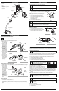
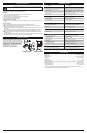
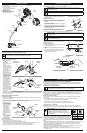
STARTING INSTRUCTIONS
1. Mix fuel with oil. Fill fuel tank with fuel/oil mixture. See Oil and Fuel
Mixing Instructions.
2. Fill the fuel tank with fresh, clean fuel mix. Refer to Fueling the Unit.
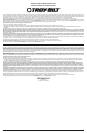
NOTE: There is no need to turn the unit on. The On/Off Control is in the
ON ( I ) position at all times (Fig. 7).
3. Fully press and release the primer bulb 10 times, slowly. Some amount
of fuel should be visible in the primer bulb and fuel lines (Fig. 8). If fuel
can not be seen in the bulb, press and release the bulb until fuel is
visible.
4. Place the choke lever in Position 1 (Fig. 8).
5. Crouch in the starting position (Fig. 9). Squeeze
the throttle control lever. Pull the starter rope 5
times.
6. Place the choke lever in Position 2 (Fig. 8)
7. Squeeze the throttle control, pull the starter rope
in a controlled motion 3 to 5 times to start
engine.
8. Keep the throttle squeezed and allow the engine
to warm up for 30 to 60 seconds.
9
. Continue squeezing the throttle control, move the
choke lever to Position 3 (Fig. 8) and continue
warming the engine for an additional 60 seconds.
The unit may be used during this time.
NOTE: Unit is properly warmed up when engine
accelerates without hesitation.
IF... the engine hesitates, return the choke lever to
Position 2 (Fig. 8) and continue warm-up.
IF... the engine does not start, go back to step 3.
IF...the engine fails to start after 2 attempts, place
the choke lever in Position 3 and squeeze the
throttle control. Pull
the starter rope out with a controlled and steady
motion 3 to 8 times. The engine should start. If
not, repeat.
IF WARM... If the engine is already warm, go back
to step 6.
STOPPING INSTRUCTIONS
1. Release the throttle control and allow the engine
to cool down by idling.
2. Press and hold the On/Off Control switch in the
OFF (O) position until the unit comes to a
complete stop (Fig. 7).
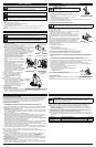
STARTING AND STOPPING INSTRUCTIONS
WARNING:
Avoid accidental starting. Make sure you are in the starting position when
pulling the starter rope (Fig. 9). To avoid serious injury, the operator and unit must be in a stable
position while starting.
WARNING:
Operate this unit in a well-ventilated outdoor area. Carbon monoxide
exhaust fumes can be lethal in a confined area.
HOW TO START THE UNIT USING THE ELECTRIC STARTER OR POWER START BIT
ACCESSORY.
NOTE: This Unit Can Use an Electric Start or Power Start Bit™ Optional Accessory!
Please refer to the Electric Starter or Power Start Bit operator’s manual for proper use of this feature.
(Items Sold Separately! Please refer to Fig. 23 of this manual about purchasing these accessories.)
STARTING INSTRUCTIONS
1. Mix fuel with oil. Fill fuel tank with fuel/oil mixture. See Oil and Fuel Mixing Instructions.
2. Fill the fuel tank with fresh, clean fuel mix. Refer to Fueling the Unit.
NOTE: There is no need to turn the unit on. The On/Off Control is in the ON ( I ) position at all times (Fig.
7).
3. Fully press and release the primer bulb 10 times, slowly. Some amount of fuel should be visible in the
primer bulb (Fig. 8). If fuel cannot be seen in the bulb, press and release the bulb until fuel is visible.
4. Move the choke lever to Position 1 (Fig. 8).
5. Crouch in the starting position (Fig. 9). Place the electric starter or power start bit into the back of the
unit. Refer to the Operation section of the Electric Starter or Power Start Bit operator’s manual.
6. Squeeze the throttle control lever. Press and hold the electric starter or drill ON (I) button for 2
seconds.
7. Move the choke lever to Position 2 (Fig. 8).
8. Squeeze the throttle control lever, press and hold the electric starter or drill ON (I) button for 2-
second intervals until the unit starts.
9.
Continue to squeeze the throttle control, remove the electric starter or drill from the unit and allow the
engine to warm up for 30 to 60 seconds.
10. Continue squeezing the throttle control, move the choke lever to Position 3 (Fig. 8) and run
the unit for an additional 60 seconds. The unit may be used during this time
NOTE: Unit is properly warmed up when engine accelerates without hesitation.
IF... the engine hesitates, return the choke lever to Position 2 (Fig. 8) and continue warm-up.
IF... the engine does not start, go back to step 3.
IF... the engine fails to start after 2 attempts, place the choke lever in Position 3 and squeeze the
throttle control. Press and hold the electric starter or drill ON (I) button for 2-second intervals until the
unit starts.
IF WARM... If the engine is alr
eady warm, start the unit with the blue choker lever in Position 2. After
the unit starts, move the blue choker lever to Position 3.
STOPPING INSTRUCTIONS
1. Release the throttle control and allow the engine to cool down by idling.
2. Press and hold the On/Off Control switch in the OFF (O) position until the unit comes to a complete
stop (Fig. 7).
IF USING THE OPTIONAL ELECTRIC STARTER OR POWER START BIT™ ACCESSORY
Fig. 8
Choke Lever
Primer Bulb
Fig. 9
Starting
Position
Starter Rope
Fig. 7
OFF (O)
ON (I)
Throttle
Control