


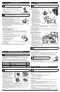

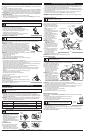
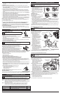


REMOVING THE LINE
1. Rotate the bump knob clockwise until all
line is inside the cutting head (Fig. 12).
2. Using a flat-head screwdriver, insert the
tip into the line dimple and just under the
exposed portion of the line (Fig. 13)
3. Pull the line straight out until all line is
removed from the cutting head.
LINE INSTALLATION
Always use original equipment manufacturer
0.095 in. (2.41 mm) replacement line.
1.
Align the arrows on the bump knob with the
spool cover eyelets, if they are not already
(Fig. 14).
2. Using 16 ft. (4.8 m) of 0.095 in. (2.41 mm)
replacement line push both ends of the line
through the holes in the bump knob until
they protrude through the eyelets on both
sides of the cutting head. Continue pulling the line until approximately 8 ft. (2.4 m) is visible from both sides
of the cutting head. (Fig. 15)
3. Hold the spool cover, turn the bump knob clockwise to wind the line around the spool until about 5
in. (12.7 cm) is protruding from each side of the cutting head. (Fig. 12)
4. Start the unit and bump the cutting head on the ground until the desired cutting length is achieved.
Excess line will be trimmed off by the line blade.
NOTE: If the cutting line ends are pulled into the cutting head or the line becomes twisted, refer to
Removing the Line.
OPERATING INSTRUCTIONS
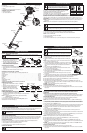
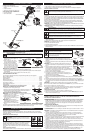
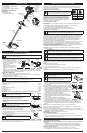
HOLDING THE UNIT
Before operating the unit, stand in the operating position (Fig. 9). Check
for the following:
• The operator is wearing eye protection and proper clothing
• With a slightly-bent right arm, the operator’s hand is holding the shaft
grip
• The operator’s left arm is straight, the left hand holding the D-handle
• The unit is at waist level
• The cutting head is parallel to the ground and easily contacts the grass
without the need to bend over
ADJUSTING TRIMMING LINE LENGTH
The Bump Head™ cutting head allows the release of trimming line without stopping the engine. To
release more line, lightly tap the cutting head on the ground (Fig. 10)
while operating the unit at high speed.
NOTE:
Always keep the trimming line fully extended. Line release becomes
more difficult when the cutting line gets shorter.
Each time the head is bumped, about 1 inch (25.4 mm) of trimming line
releases. A blade in the cutting head shield will cut the line to the
proper length if any excess line is released.
For best results, tap the bump knob on bare ground or hard soil. If
attempting a line release in tall grass, the engine may stall. Always keep
the trimming line fully extended. Line release becomes more difficult when the cutting line gets shorter.
NOTE: Do not rest the Bump Head™ on the ground while the unit is running.
Some line breakage will occur from:
• Entanglement with foreign matter
• Normal line fatigue
• Attempting to cut thick, stalky weeds
• Forcing the line into objects such as walls or fence posts
TIPS FOR BEST TRIMMING RESULTS
• Keep the cutting head parallel to the ground.
• Do not force the cutting head. Allow the tip of the line to do the cutting, especially along walls.
Cutting with more than the tip will reduce cutting efficiency and may overload the engine.
• Cut grass over 8 inches (200 mm) by working from top to bottom in small increments to avoid
premature line wear or engine drag.
• Cut from right to left whenever possible. Cutting to the left improves the unit's cutting efficiency.
Clippings are thrown away from the operator.
• Slowly move the unit into and out of the cutting area at the desired
height. Move either in a forward-backward or side-to-side motion.
Cutting shorter lengths produces the best results.
• Trim only when grass and weeds are dry.
• The life of the cutting line is dependent upon:
• Following the trimming techniques
• What vegetation is being cut
• Where vegetation is cut
For example, the line will wear faster when trimming against a foundation wall as opposed to
trimming around a tree.
DECORATIVE TRIMMING
Decorative trimming is accomplished by removing all vegetation around trees, posts, fences, etc..
Rotate the whole unit so that the cutting head is at a 30° angle to the ground (Fig. 11).
W
ARNING:
Always wear eye, hearing, foot and body protection to reduce the risk of injury when operating
this unit.
WARNING:
Do not remove or alter the line cutting blade assembly. Excessive line length will cause
premature engine failure and / or unit damage.
F
ig. 9
4
Fig. 10
Fig. 11
MAINTENANCE AND REPAIR INSTRUCTIONS
WARNING:
Never use metal-reinforced line, wire, chain or rope. These can break off and become
dangerous projectiles.
M
AINTENANCE SCHEDULE
Perform these required maintenance procedures at the frequency stated in the table. These
procedures should also be a part of any seasonal tune-up.
NOTE: Some maintenance procedures may require special tools or skills. If you are unsure about these
procedures take your unit to any non-road engine repair establishment, individual or authorized
service dealer.
NOTE: Maintenance, replacement, or repair of the emission control devices and system may be
performed by any non-road engine repair establishment, individual or authorized service dealer.
NOTE: Please read the California/EPA statement that came with the unit for a complete listing of terms
and coverage for the emissions control devices, such as the spark arrestor, muffler, carburetor, etc.
WARNING:
To prevent serious injury, never perform maintenance or repairs with unit running. Always
s
ervice and repair a cool unit. Disconnect the spark plug wire to ensure that the unit cannot start.
FREQUENCY MAINTENANCE REQUIRED SEE
Before starting engine Fill fuel tank with fresh fuel p. 3
Every 10 hours Clean and re-oil air filter p. 4
Every 25 hours Check spark plug condition and gap p. 4
CLEANING AND STORAGE
CLEANING
Use a small brush to clean off the outside of the unit. Do not use strong detergents. Household
cleaners that contain aromatic oils such as pine and lemon, and solvents such as kerosene, can
damage plastic housing or handle. Wipe off any moisture with a soft cloth.
STORAGE
• Never store a fueled unit where fumes may reach an open flame or spark.
• Allow the engine to cool before storing.
• Store the unit locked up to prevent unauthorized use or damage.
• Store the unit in a dry, well-ventilated area.
• Store the unit out of the reach of children.
Short Term Storage (1-2 weeks)
1. Store the unit in a horizontal position. If this is not possible, store the unit vertically with the engine at
the top.
Long-term Storage
1. Remove the fuel cap, tip the unit and drain the fuel into an approved container.
NOTE: Do not use gasoline that has been stored for more than 30 days. Dispose of old gasoline in
accordance with federal, state and local regulations.
2. Start the engine and allow it to run until it stalls. This ensures that all fuel has been drained from the
carburetor.
3. Allow the engine to cool. Remove the spark plug and put 5 drops of any high quality motor oil or 2-
cycle oil into the cylinder. Pull the starter rope slowly to distribute the oil. Reinstall the spark plug.
NOTE: Remove the spark plug and drain all of the oil from the cylinder before attempting to start the
unit after storage.
4. Thoroughly clean the unit and inspect it for any loose or damaged parts. Repair or replace damaged
parts and tighten loose screws, nuts or bolts. The unit is ready for storage.
WARNING:
To avoid serious personal injury, always turn the unit off and allow it to cool before you
clean or service it.
Fig. 15
Fig. 13
Fig. 12
Arrows
Eyelet
Fig. 14
Bump
Knob
Trimmer
Line
Flat-Head
Screw Driver
Dimple
Trimmer Line
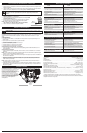
AIR FILTER MAINTENANCE
Cleaning the Air Filter
Failure to maintain your air filter
properly can result in poor
performance or can cause permanent
damage to your engine.
1. Open the air filter cover by
unscrewing the cover screw (Fig. 16).
2. Remove the air filter and the
screen that sits behind it (Fig. 16).
3. Wash the filter in detergent and
water. Rinse the filter thoroughly
and allow it to dry.
4. Apply enough clean SAE 30 motor
oil to lightly coat the filter.
5. Squeeze the filter to spread and
remove excess oil.
6. Replace the air filter and the
screen that sits behind it (Fig. 16).
NOTE: Operating the unit without the
air filter will VOID the warranty.
7. Reinstall the air filter cover. Insert
the hooks on the air filter housing
into the slots on the air filter cover
(Fig. 16).
8. Swing the air filter cover to the
right and align the cover screw
with the cover screw hole (Fig.
16). Tighten the cover screw to secure the air filter cover.
NOTE: Do not over tighten as this may strip the screw.
IDLE SPEED ADJUSTMENT
The idle speed of the engine is adjustable. An idle adjustment screw is between the air filter cover and
the engine starter housing (Fig. 17).
NOTE: Careless adjustments can seriously damage the unit. An authorized service dealer should make
carburetor adjustments.
If, after checking the fuel mixture and
cleaning the air filter, the engine still will
not idle, adjust the idle speed screw as
follows:
1. Start the engine and run for one minute
to warm up. Refer to Starting and
Stopping Instructions.
2. Release the throttle trigger and let the
engine idle. If the engine stops, insert a
small Phillips screwdriver into the idle
adjustment screw (Fig. 17). Turn the idle
speed screw clockwise 1/8 of a turn at
a time (as needed) until the engine idles
smoothly.
3. If the engine appears to be idling too
fast, turn the idle speed screw
counterclockwise 1/8 of a turn at a
time (as needed), to reduce idle speed.
Checking the fuel mixture, cleaning the air filter and adjusting the idle speed should solve most engine
problems. If not and all of the following are true:
• the engine will not idle
• the engine hesitates or stalls on acceleration
• there is a loss of engine power
Have the carburetor adjusted by an authorized service dealer.
REPLACING THE SPARK PLUG
Use replacement #753-06193, a Champion RDJ7J spark plug, or equivalent. The correct air gap is 0.025
inch (0.635 mm). Remove the plug after every 25 hours of operation and check its condition.
1. Stop the engine and allow it to cool. Grasp the plug wire firmly and pull it from the spark plug.
2.
Clean around the spark plug. Remove the spark plug from the cylinder head by turning a 5/8-inch socket
counterclockwise.
3. Replace a cracked, fouled or dirty spark plug. Set the air gap at 0.025 in.
(0.635 mm) using a feeler gauge (Fig. 18).
4. Install a correctly-gapped spark plug in the cylinder head. Tighten by
turning the 5/8-inch socket clockwise until snug.
If using a torque wrench torque to: 110-120 in.•lb. (12.3-13.5 N•m)
Do not over tighten.
WARNING:
To avoid serious personal injury, always turn the unit off and allow it to cool before you
clean or service it.
WARNING:
T
he cutting attachment will spin during idle speed adjustments. Wear protective clothing
and observe all safety instructions to prevent serious personal injury.
WARNING:
Do not sand blast, scrape or clean electrodes. Grit in
t
he engine could damage the cylinder.
Fig. 18
0
.025 in.
(0.635 mm.)
MAINTENANCE AND REPAIR INSTRUCTIONS
Fig. 16
H
ooks
A
ir Filter
Cover
C
over Screw
Hole
A
ir Filter
Housing
S
lots
Air Filter
A
ir Filter
Housing
A
ir Filter Cover
Cover
Screw
Idle Speed Screw
Fig. 17