


STARTING INSTRUCTIONS
1. Mix fuel with oil. Fill fuel tank with fuel/oil mixture. See Oil and Fuel
Mixing Instructions.
2. Fill the fuel tank with fresh, clean unleaded fuel. Refer to Fueling the
Unit.
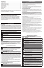
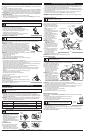
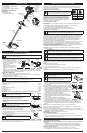
NOTE: There is no need to turn the unit on. The On/Off Control is in the
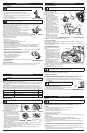
ON ( I ) position at all times (Fig. 6).
3. Fully press and release the primer bulb 10 times, slowly. Some amount
of fuel should be visible in the primer bulb and fuel lines (Fig. 7). If fuel
can not be seen in the bulb, press and release the bulb until fuel is
visible.
4. Place the choke lever in Position 1 (Fig. 7).
5. Crouch in the starting position (Fig. 8). Squeeze the throttle control
lever. Pull the starter rope 5 times.
6. Place the choke lever in Position 2 (Fig. 7)
7. Squeeze the throttle control, pull the starter rope in a controlled motion
3 to 5 times to start engine.
8. Keep the throttle squeezed and allow the engine to warm up for 30 to
60 seconds.
9. Continue squeezing the throttle control, move the choke lever to Position 3 (Fig. 7) and continue
warming the engine for an additional 60 seconds. The unit may be used during this time.
NOTE: Unit is properly warmed up when engine accelerates without hesitation.
IF... the engine hesitates, return the choke lever to Position 2 (Fig. 7) and continue warm-up.
IF... the engine does not start, go back to step 3.
IF... the engine fails to start after 2 attempts, place the choke lever in Position 3 and squeeze the
throttle control. Pull the starter rope out with a controlled and steady motion 3 to 8 times. The engine
should start. If not, repeat.
IF WARM... If the engine is already warm, go back to step 6.
STOPPING INSTRUCTIONS
1. Release the throttle control and allow the engine to cool down by idling.
2. Press and hold the On/Off Control switch in the OFF (O) position until the unit comes to a complete
stop (Fig. 6).
The bottle of 2-cycle oil contains a fuel additive which will help inhibit
corrosion and minimize the formation of gum deposits. It is
recommended to use our 2-cycle oil with this unit.
If unavailable, use a good 2-cycle oil designed for air-cooled engines
along with a fuel additive, such as STA-BIL® Gas Stabilizer or an
equivalent. Add 0.8 oz. (23 ml.) of fuel additive per gallon of fuel
according to the instructions on the container. NEVER add fuel additives directly to the unit's fuel tank.
Thoroughly mix the proper ratio of 2-cycle engine oil with unleaded fuel in a separate fuel can. Use a
40:1 fuel/oil ratio. Do not mix them directly in the engine fuel tank. See the table for specific gas and oil
mixing ratios.
NOTE:
One gallon (3.8 liters) of unleaded fuel mixed with one 3.2 oz. (95 ml.) bottle of 2-cycle oil makes a 40:1
fuel/oil ratio.
NOTE: Dispose of the old fuel/oil mix in accordance to federal, state and local regulations.
FUELING THE UNIT
1. Turn unit on its side, with the fuel cap facing up, and remove the fuel cap.
2. Place the gas container’s spout into the fill hole on the fuel tank and fill the tank.
NOTE: Do not overfill the tank.
3. Wipe up any gasoline that may have spilled.
4. Reinstall the fuel cap.
5. Move the unit at least 30 ft. (9.1 m) from the fueling source and site before starting the engine.
OIL AND FUEL MIXING INSTRUCTIONS
Old and/or improperly mixed fuel are the main reasons for the unit not running properly. Be sure to use
fresh, clean unleaded fuel. Follow the instructions carefully for the proper fuel/oil mixture.
DEFINITION OF BLENDED FUELS
Today's fuels are often a blend of gasoline and oxygenates such as ethanol, methanol, or MTBE (ether).
Alcohol-blended fuel absorbs water. As little as 1% water in the fuel can make fuel and oil separate. It
forms acids when stored. When using alcohol-blended fuel, use fresh fuel (less than 60 days old).
USING BLENDED FUELS
If choosing to use a blended fuel, or its use is unavoidable, follow recommended precautions:
• Always use the fresh fuel mix explained in the operator's manual
• Always agitate the fuel mix before fueling the unit
• Drain the tank and run the engine dry before storing the unit
USING FUEL ADDITIVES
M
IXING RATIO - 40:1
3
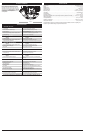
OIL AND FUEL INFORMATION
U
NLEADED GAS
2
CYCLE OIL
1
GALLON US
(
3.8 LITERS)
3
.2 FL. OZ.
(
95 ml)
1
LITER
2
5 ml
CAUTION:
For proper engine operation and maximum reliability, pay strict attention to the oil and fuel
mixing instructions on the 2-cycle oil container. Using improperly mixed fuel can severely damage the engine.
WARNING:
G
asoline is extremely flammable. Ignited vapors
m
ay explode. Always stop the engine and allow it to cool
b
efore filling the fuel tank. Do not smoke while filling the tank.
Keep sparks and open flames at a distance from the area.
WARNING:
R
emove fuel cap slowly to avoid injury from fuel spray. Never operate the unit without the
fuel cap securely in place.
WARNING:
Add fuel in a clean, level and well ventilated outdoor area. Wipe up any spilled fuel immediately.
Avoid creating a source of ignition for spilled fuel. Do not start the engine until fuel vapors dissipate.
STARTING/STOPPING INSTRUCTIONS
WARNING:
A
void accidental starting. Make sure you are in the
starting position when pulling the starter rope (Fig. 8). To avoid serious
injury, the operator and unit must be in a stable position while starting.
O
FF (O)
ON (I)
Throttle
C
ontrol
F
ig. 6
Starter
R
ope
Starting Position
Fig. 8
Fig. 7
Primer Bulb
Choke Lever
WARNING:
It has been proven that fuel containing greater than 10% ethanol will likely damage this engine
and void the warranty.
W
ARNING:
Operate this unit in a well-ventilated outdoor area.
C
arbon monoxide exhaust fumes can be lethal in a confined area.
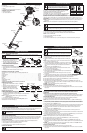
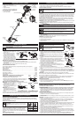
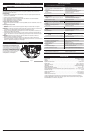
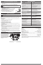
KNOW YOUR UNIT
APPLICATIONS
As a trimmer:
• Cutting grass and light weeds.
• Edging
• Decorative trimming around trees, fences, etc.
ASSEMBLY TOOLS REQUIRED
• Phillips screwdriver
• 3/8” Socket and driver
T
hrottle Control
D
-Handle
Shaft Grip
Air Filter
Cover
S
park Plug
S
haft Housing
Starter Rope Grip
Line Cutting
Blade
Muffler
On/Off Control
C
utting Head
Cutting Head Shield
Fuel Cap
C
hoke Lever
P
rimer
Bulb
HOW TO START THE UNIT USING THE ELECTRIC STARTER OR POWER START BIT
ACCESSORY.
NOTE: This Unit Can Use an Electric Start or Power Start Bit™ Optional Accessory!
Please refer to the Electric Starter or Power Start Bit operator’s manual for proper use of this feature.
(Items Sold Separately! Please refer to page 5 of this manual about purchasing these accessories.)
STARTING INSTRUCTIONS
1. Mix fuel with oil. Fill fuel tank with fuel/oil mixture. See Oil and Fuel Mixing Instructions.
2. Fill the fuel tank with fresh, clean fuel mix. Refer to Fueling the Unit.
NOTE: There is no need to turn the unit on. The On/Off Control is in the ON ( I ) position at all times (Fig. 6).
3. Fully press and release the primer bulb 10 times, slowly. Some amount of fuel should be visible in the
primer bulb (Fig. 7). If fuel cannot be seen in the bulb, press and release the bulb until fuel is visible.
4. Move the choke lever to Position 1 (Fig. 7).
5. Crouch in the starting position (Fig. 8). Place the electric starter or power start bit into the back of the
unit. Refer to the Operation section of the Electric Starter or Power Start Bit operator’s manual.
6. Squeeze the throttle control lever. Press and hold the electric starter or drill ON (I) button for 2
seconds.
7. Move the choke lever to Position 2 (Fig. 7).
8. Squeeze the throttle control lever, press and hold the electric starter or drill ON (I) button for 2-
second intervals until the unit starts.
9. Continue to squeeze the throttle control, remove the electric starter or drill from the unit and allow the
engine to warm up for 30 to 60 seconds.
10.Continue squeezing the throttle control, move the choke lever to Position 3 (Fig. 7) and run the unit
for an additional 60 seconds. The unit may be used during this time.
NOTE: Unit is properly warmed up when engine accelerates without hesitation.
IF... the engine hesitates, return the choke lever to Position 2 (Fig. 7) and continue warm-up.
IF... the engine does not start, go back to step 3.
IF... the engine fails to start after 2 attempts, place the choke lever in Position 3 and squeeze the
throttle control. Press and hold the electric starter or drill ON (I) button for 2-second intervals until the
unit starts.
IF WARM... If the engine is already warm, start the unit with the blue choker lever in Position 2. After
the unit starts, move the blue choker lever to Position 3.
STOPPING INSTRUCTIONS
1. Release the throttle control and allow the engine to cool down by idling.
2. Press and hold the On/Off Control switch in the OFF (O) position until the unit comes to a complete
stop (Fig. 6).
IF USING THE OPTIONAL ELECTRIC STARTER OR POWER START BIT™ ACCESSORY
OIL AND FUEL INFORMATION
EZ-Link™
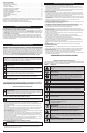
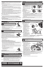
INSTALL THE CUTTING HEAD SHIELD
1. Place the cutting head shield onto the
guard mount bracket, making sure to
align the holes on the shield with the ones
in the guard mount bracket. (Fig. 1)
2. Take the 4 shield screws and screw each
one into the shield until finger tight.
3. Using a Phillips screw driver, tighten the
screws until the shield is firmly in place.
ADJUSTING THE D-HANDLE
1. Loosen the bolt on the handle just enough to move it (Fig. 2).
2.
While holding the unit in the operating position (Fig. 9), move the D-handle to the location that provides the
best grip.
3. Tighten the bolt until the D-handle is secure. (Fig. 2)
OPERATING THE RAPID-LINK™ SYSTEM
The Rapid-Link™ system enables the use of these optional Add-Ons.
Trimmer. . . . . . . . . . . . . . . . . . . . . . . . . . . . . . . . . . . . . . . . . . . . . . . . . . . . . . . . . . . . . . . . . . . . . . . AF720
Hedge Trimmer*. . . . . . . . . . . . . . . . . . . . . . . . . . . . . . . . . . . . . . . . . . . . . . . . . . . . . . . . . . . . . . . AH720*
Brushcutter* . . . . . . . . . . . . . . . . . . . . . . . . . . . . . . . . . . . . . . . . . . . . . . . . . . . . . . . . . . . . . . . . . . BC720*
Cultivator . . . . . . . . . . . . . . . . . . . . . . . . . . . . . . . . . . . . . . . . . . . . . . . . . . . . . . . . . . . . . . . . . . . . GC720
Edger*. . . . . . . . . . . . . . . . . . . . . . . . . . . . . . . . . . . . . . . . . . . . . . . . . . . . . . . . . . . . . . . . . . . . . . . LE720*
Pole Saw . . . . . . . . . . . . . . . . . . . . . . . . . . . . . . . . . . . . . . . . . . . . . . . . . . . . . . . . . . . . . . . . . . . . . PS720
Straight Shaft Trimmer . . . . . . . . . . . . . . . . . . . . . . . . . . . . . . . . . . . . . . . . . . . . . . . . . . . . . . . . . . SS725
Turbo Blower . . . . . . . . . . . . . . . . . . . . . . . . . . . . . . . . . . . . . . . . . . . . . . . . . . . . . . . . . . . . . . . . . . TB720
* Do NOT use this Add-On with an electric powered unit.
REMOVING THE ADD-ON
1. Turn the knob counterclockwise to loosen
(Fig. 5).
2. Press and hold the release button (Fig. 3).
3. While firmly holding the upper shaft
housing, pull the lower shaft housing
straight out of the Rapid-Link™ coupler
(Fig. 4).
INSTALLING THE ADD-ON
NOTE: To make installing or removing the
add-on easier, place the unit on the ground or on a work bench.
1. Turn knob counterclockwise to loosen (Fig. 5).
2. While firmly holding the add-on, push it straight into the Rapid-Link™
coupler (Fig. 4).
NOTE: Aligning the release button with the guide recess will help
installation (Fig. 3).
3. Turn the knob clockwise to tighten (Fig. 5).
For decorative trimming/edging with the line cutting head, lock the
release button into the 90° hole (Fig. 5).
ASSEMBLY INSTRUCTIONS
WARNING:
To prevent serious personal injury, never operate the trimmer without the cutting
a
ttachment shield in place.
G
uide Recess
Fig. 3
R
elease
Button
Rapid-Link™
Coupler
Upper Shaft
H
ousing
Fig. 4
Lower Shaft
H
ousing
Primary Hole
Knob
Fig. 5
90˚ Edging Hole
(Trimmer Only)
D
-Handle
Bolt
Fig. 2
6 in.
(
15.24 cm)
Minimum
F
ig. 1
Guard
M
ount
Bracket
S
crew (4
)
Cutting
Head Shield