


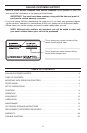
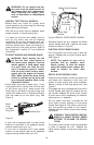
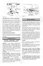
height. With the spring washer on the axle
bolt reinsert in the square hole desired,
through the wheel assembly and secure with
the wing nut previously removed.
IMPORTANT: All wheels must be placed in
the same relative position.
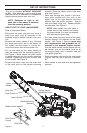
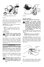
NOTE: For rough or uneven lawns,
move the height adjustment lever to a
higher position. This will help stop
scalping.
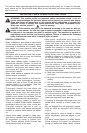
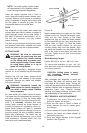
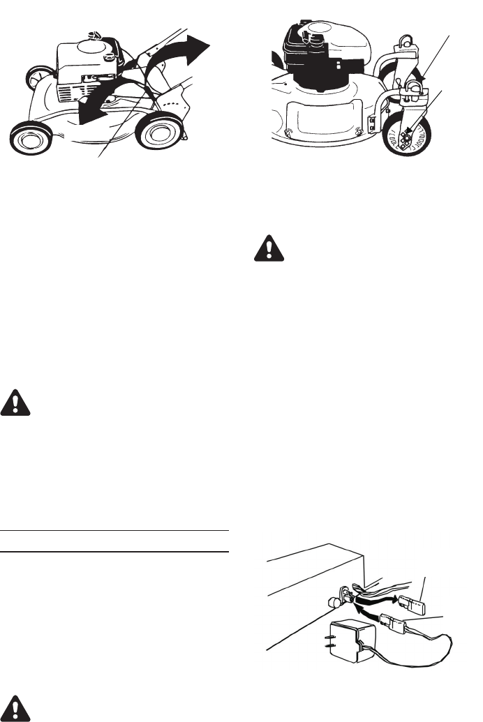
CASTER LOCK
WARNING: When operating mower
on hills, front wheels should be
locked in the straight ahead posi-
tion.
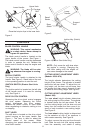
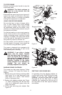
The casters can be locked in a straight
ahead position or can be left to swivel freely.
Lift and place the lock pins in the larger
holes for locked, straight ahead operation,
place pins in smaller holes to allow casters
to rotate freely.
OPERATION
IMPORTANT: Move the shift lever ONLY
when the engine is running. Shifting the
speeds with the engine off can cause dam
-
age to the unit. Disengage the drive clutch
control before changing the speed selection.
Service the engine with gasoline and oil as
instructed in the separate engine manual
packed in your mower. Read instructions
carefully.
WARNING: Never fill fuel tank in
-
doors, with engine running or until
the engine has been allowed to cool
for at least two minutes after run
-
ning.
BEFORE STARTING
MODELS WITH ELECTRIC START ONLY:
WARNING: The battery contains
corrosive fluid and toxic material.
HANDLE WITH CARE. Keep away
from children. Do not puncture, dis
-
assemble, mutilate or incinerate. Ex
-
plosive gases could be vented dur
-
ing charging or discharging. Use in
a well-ventilated area, away from
sources of ignition.
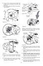
•
Charge battery for 16 hours before initial
use. DO NOT CHARGE LONGER THAN 20
HOURS.
IMPORTANT: Use only the battery
charger supplied with this mower.
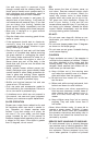
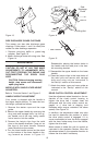
To charge the battery, first remove the pro-
tective cap from the end of the battery pack
lead. Always plug charger lead into battery
pack lead before inserting battery charger
plug into 120 volt standard household outlet.
See Figure 7.
After charging, disconnect battery charger
plug from household outlet first, then discon
-
nect charger lead from battery pack lead.
9
Figure 6
Locking Pin
Axle Bolt
and
Spring
Washer
Figure 5
Cutting Height Adjustment Lever
LOWER
HIGHER
Figure 7
Protective
Cap
Battery
pack