


CONTROLS
BLADE CONTROL HANDLE
WARNING: This control mechanism
is a safety device. Never attempt to
bypass its operations.
The blade control handle is located on the
upper handle of the mower. See Figure 1.
The blade control handle must be depressed
in order to operate the unit. Release the
blade control handle to stop the engine and
blade.
WARNING: The blade will be rotat-
ing whenever the engine is running.
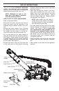
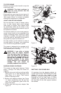
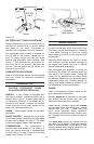
RECOIL STARTER
The recoil starter handle is attached to the
handle. See Figure 3. Stand behind the unit
in the operating position to start the unit.
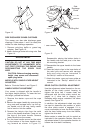
IGNITION SWITCH (Electric Start Units
Only)
The ignition switch is located on the left side
of the handle panel. It is used for starting
only. See Figure 4.
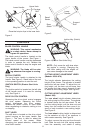
DRIVE CLUTCH CONTROL
Squeezing the drive clutch control engages
the drive system. Releasing the clutch
control disengages the drive system.
Release the clutch control to slow down
when negotiating an obstacle, making a turn
or stopping.
SHIFT LEVER
The shift lever is located on the drive clutch
control housing on the upper handle. See
Figure 1. This lever is used to select the
forward speed of the mower. When
changing your speed selection, release the
drive clutch control.
NOTE: Only move the shift lever when
the engine is running. Changing the
shift lever setting with the engine off
can cause damage to the mower.
CUTTING HEIGHT ADJUSTMENT LEVER
(Models: 959 & 979)
The height adjuster determines the cutting
height of the mower. The adjuster is located
above the left rear wheel. To adjust the cut
-
ting height, pull the lever out and away from
the mower and then move it forward or back
to select a new cutting height. See Figure 5.
CUTTING HEIGHT ADJUSTMENT LEVER
(Model: 999)
The rear wheel height adjuster determines
the cutting height of the mower. The adjuster
is located above the left rear wheel. To ad
-
just the cutting height, pull the lever out and
away from the mower and then move it for
-
ward or back to select a new cutting height.
See Figure 5.
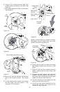
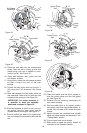
The front wheel cutting height is determined
by the selection of one of six positions in
each caster assembly. See Figure 6.
To adjust, remove the wing nut from the axle
bolt. Slide the axle bolt and spring washer
from the assembly and select a cutting
8
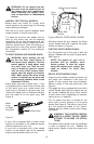
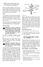
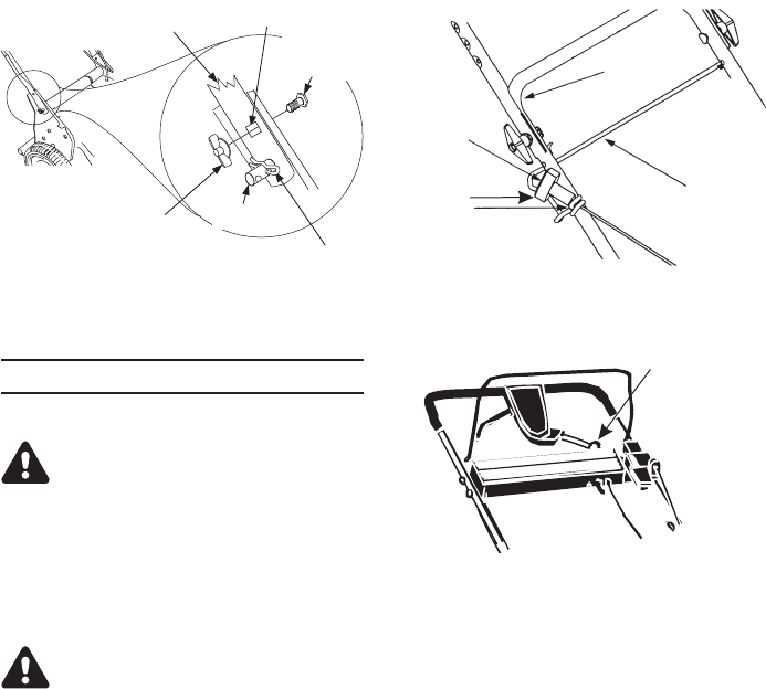
Figure 2
Carriage
Bolt
Wing Nut
Upper Hole
Place the hairpin clips in the inner hole.
Weld Pin
Lower Handle
Figure 4-(Electric Start Units Only)
Ignition Key (Switch)
Figure 3
Rope
Guide
Recoil
Starter
Lower
Handle
Support
Rod