


AttachingBeam
• For shipping purposes, the pressure hose is
attached to the pump on the engine and to the
control valve on the cylinder.
• Disconnect the pressure hose from the adapter on
the pump.
• Stand the wedge, beam, and cylinder assembly
upright with cylinder toward the top. An assistant
may be helpful.
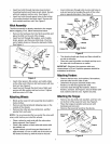
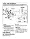
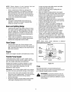
• Remove cotter pin and clevis pin from welded
brackets on beam assembly and move the
reservoir tank assembly in position against the
beam.
• Insert clevis pin just removed through brackets on
beam and reservoir tank assembly. Secure with
cotter pin by bending the ends of the pin in opposite
directions. See Figure 7.
Clevis
Pin_
Cotter
_S Pin
Brackets
Reservoir
Tank
Figure 7
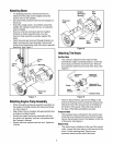
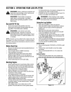
AttachingEngine-PumpAssembly
• Place the engine and pump assembly in position on
the engine mounting bracket with the pump facing
out. See Figure 8.
• Align holes in base of engine with appropriate holes
in engine mounting bracket.
• Secure the engine and pump assembly with four
hex bolts, lock washers, and hex nuts packed with
the Operator's Manual.
• Secure with lock washers and hex nuts. Tighten to
14 ft-lbs.
Engine Hex
Mounting
Bracket
Reservoir
Tank
Washer
Hex
Bolts
Pump
Facing
Out
Figure 8
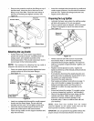
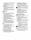
AttachingThe Hoses
SuctionHose
• The suction is attached to the reservoir tank,
beneath the engine mounting bracket. Loosen the
hose clamp on the free end of the hose. Remove
any protective insert from the end of the hose. See
Figure 9.
Pressure Attached
Engine
Attached To
Pum Reservoir Tank
Hose
Clam
Suction Hose
Figure 9
• Remove the protective cap from the fitting on the
bottom of the pump (some oil may flow from pump).
Attach the end of the suction hose to the fitting on
the bottom of the pump. Place the hose clamp at
the base of the fitting and tighten securely.
PressureHose
• The pressure hose is attached to the control valve.
Route the hose between the beam and the tongue.
Secure the pressure hose to the adapter on the top
of the pump. See Figure 9.
ReturnHose
• The return hose is attached to the top of the control
valve. Loosen the hose clamp on the free end of the
hose. Cut the securing strap. Remove any
protective insert from the end of the hose.