


NOTE: Please dispose of used hydraulic fluid and
engine oil at approved recycling centers only.
• Since contaminants in fluid may damage the
hydraulic components, you will have to drain the
fluid and flush the reservoir tank and hoses with
kerosene whenever any repair work is performed
on the tank, hydraulic pump or valve. For this job,
contact your nearest service dealer.
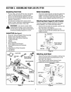
HydraulicFilter
• Change the hydraulic filter every 50 hours of
operation. Use only a 10 micron hydraulic filter.
Order part number 723-0405.
BeamandSplittingWedge
• Lubricate both sides of the beam (where it comes
into contact with the splitting wedge), before each
use, with engine oil. The wedge plate on the log
splitter is designed so the gibs on the side of the
wedge plate can be removed and rotated and/or
turned over for even wear.
• Make certain to readjust the adjustment bolts so
wedge moves freely, but no excess space exists
between the wedge plate and the beam.
HoseClamps
• Check, before each use, if hose clamps on the
suction hose (attached to the side of the pump) are
tight. Check the hose clamps on the return hose at
least once a season.
Engine
Refer to the engine manual for all maintenance needs.
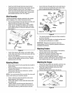
FlexiblePumpCoupler
The flexible pump coupler is a nylon "spider" insert,
located between the pump and the engine shaft. Over
time, the coupler will harden and deteriorate.
Replace the coupler if you detect vibration or noise
coming from the area between the engine and the
pump. If the coupler fails completely, you will
experience a loss of power.
IMPORTANT: Never hit the engine shaft in any manner,
as a blow will cause permanent damage to the engine.
• Remove three nuts and lock washers that secure
the pump to the coupling shield. Two nuts are at the
bottom corners and one is in the top center.
• Remove the pump.
• Rotate the engine by slowly pulling starter handle
until engine coupling half set screw is visible.
Loosen set screw using allen wrench and slide
coupling half off engine shaft.
• Loosen set screw on pump coupling half and
remove coupling half.
• Slide new engine coupling half onto the engine
shaft until the end of the shaft is flush with the inner
portion of the coupling half. (There must be space
between end of the engine support bracket and
coupling half). Tighten set screw.
• Install pump coupling half and key on pump shaft.
Rotate coupling half until set screw faces opening
in shield. Do not tighten set screw.
• Install nylon "spider" onto engine coupling half.
• Align pump coupling half with nylon "spider" by
rotating engine using starter handle. Slide coupling
half into place while guiding three mounting bolts
through holes in pump support bracket.
• Secure with nuts and washers removed earlier.
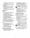
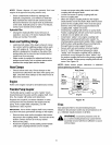
• Set.010" to.060" clearance between the nylon
"spider" and the engine coupling half by sliding a
matchbook cover between the nylon "spider" and
the engine coupling half and moving pump coupling
half as needed. Secure pump coupling half with set
screw. See Figure 16.
NOTE: Make certain proper clearance is obtained
before tightening set screw.
Gear Pump
Set
Sc:e:_ _ r_ j _ _ Steel
"S;ider"_.__ _ Coupling
Insert _ Halves
Clearance_
Figure 16
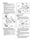
Tires
See sidewall of tire for recommended pressure.
Maximum tire pressure under any circumstances is 30
p.s.i. Maintain equal pressure on all tires.
WARNING: Excessive pressure (over 30
_L, p.s.i.) when seating beads cause tire/rim
may
assembly to burst with force sufficient to cause
serious injury.
14