


7
3
Prior to operating
your snow thrower,
refer to Auger Control
on page 9. Read and
follow all instructions
carefully and perform
all adjustments to
verify your unit is
operating safely and
properly.
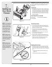
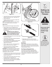
Setting Up
Your Snow
Thrower
WARNING
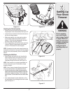
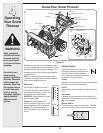
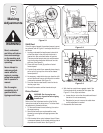
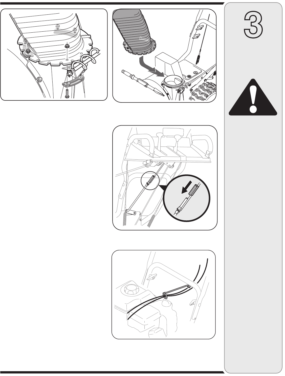
Attaching the Chute Assembly
• Removelocknutsandscrewssecuringoneofthe
flange keepers to the chute assembly. See Figure 3-4.
• Loosenbutdonotremovethelocknutsandscrewson
the other two flange keepers.
• Slide chute assembly over chute opening, making
sure the flange keepers are beneath lip of chute
adapter. The notches should engage with the spiral
end of the chute crank. See Figure 3-5.
• Secureflangekeeper,locknutsandscrewspreviously
removed. Tighten all flange keepers and hardware
with two 7/16” wrenches. Do not over tighten.
NOTE: If necessary the chute crank support bracket can
be adjusted so the spiral on the chute crank fully engages
the teeth on the chute assembly. Refer to the Adjustment
Section.
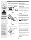
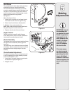
Attaching the Shift Rod
• Aligntheupperandlowershiftrods,then slide the
shift rod connector down over the end of the lower
shift rod. Tap the connector until the lower rod is
completely through the connector. See Figure 3-6.
NOTE: If the connector is not properly assembled, the
shift rod will pivot and you will not be able to change
speeds or direction.
NOTE: If the full range of speeds (forward and reverse)
cannot be achieved, refer to the Adjustment Section.
• Normally the cable ties holding the steering cables
against the handle are loosely installed on each side
of the lower handle at the factory. Pull the cable ties
tight to secure. Cut the excess from the ends of cable
ties.
• Ifnotalreadyattached,slipthecablesthatrunfrom
the handle panel to the discharge chute into the cable
guide. See Figure 3-7.
Figure 3-4
Figure 3-5
Figure 3-6
Figure 3-7