


SECTION2: ASSEMBLY
WARNING: Toprevent
personalinjury or property
damage,do notstartthe engine
until all assemblysteps are
completeandyou haveread
and understandthesafety and
operatinginstructions in this
manual.
INTRODUCTION
Carefullyfollow these assemblysteps to
correctly prepareyour tiller for use. It is
recommendedthatyou readthis Sectionin
its entirety beforebeginning assembly.
NOTE: Various rifler models are
presented in this Manual. Use only the
information appropriate for your tiller
model. Engine styles vary by model, Your
engine may appear differently than those
illustrated in this manual.
INSPECTUNIT
Inspect the unitand carton for damageim-
mediatelyafter delivery.Contactthe carrier
(trucking company) if you find or suspect
damage. Inform them of the damageand
request instructions for filing a claim. To
protect your rights, put your claim in writ-
ing and mail a copyto the carrierwithin 15
days after the unit has beendelivered.
ContactTroy-Bilt LLCif you needassis-
tance in this matter.
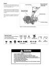
TOOLS/ MATERIALSNEEDED
(2) 1/2" open-end wrench*
(2) 9/16" open-endwrench*
(1) 3/8" open-endwrench*
(1) Largeadjustable wrench
(Models 644A only)
(1) Scissors (totrim plasticties)
(1) Ruler (for belttension check)
(1) Block of wood (to support tiller when
removing wheels)
(1) Tire pressure gauge (for models with
pneumatictires)
(1) Cleanoil funnel
(1) Motor oil. Refertothe EngineOwner's
Manualfor oil specificationsand
quantityrequired.
* Adjustable wrenchesmay be used.
ASSEMBLYSTEPS
STEP 1: UNPACKING INSTRUCTIONS
NOTE:While unpacking,do not severely
bend anycontrol cables.
1.Thetiller weighs approximately 133 Ibs.
Do notattempt to remove it from the ship-
ping platform until instructed to do so in
these Assembly steps.
2. Removeany packagingmaterial from
the carton. Removeany staplesfrom the
bottom of the carton and removethe car-
ton from the shipping platform.
3. Removeall unassembledparts andthe
separatehardware bag from the carton.
Checkthat you havethe items listed in the
LooseParts List (contactyour localdealer
or the factory itemsare missing or dam-
aged).
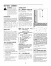
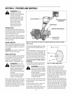
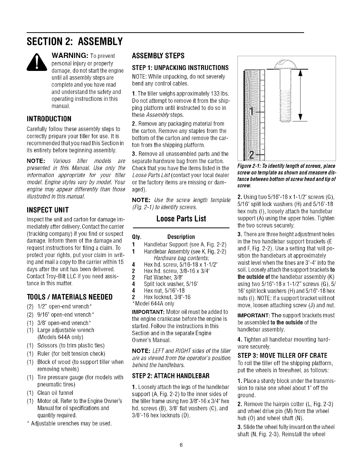
NOTE: Use the screw length template
(Fig,2-1) to identify screws,
LooseParts List
Qty. Description
1 HandlebarSupport (seeA, Fig. 2-2)
1 HandlebarAssembly(seeK,Fig.2-2)
Hardwarebag contents:
4 Hexhd. screw, 5/16-18 x 1-1/2"
2 Hexhd. screw, 3/8-16 x 3/4"
2 FlatWasher,3/8"
4 Split lockwasher,5/16"
4 Hex nut, 5/16"-18
2 HexIocknut, 34}"-16
*Model 644A only
IMPORTANT:Motor oil must beaddedto
the enginecrankcasebeforetheengine is
started. Followthe instructions inthis
Sectionand in the separateEngine
Owner's Manual.
NOTE: LEFTand RIGHTsides of thetiller
are as viewedfrom theoperator's position
behind thehandlebars.
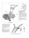
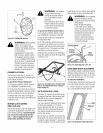
STEP 2: ATTACHHANDLEBAR
1. Looselyattachthe legsof thehandlebar
support (A, Fig. 2-2) to the inner sides of
the tiller frame usingtwo 3/8"-16x 3/4" hex
hd. screws (B), 3/8" flat washers(C), and
3/8"-16 hex Iocknuts (D).
_iiii
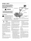
Figure2-1: Toidentifylengthofscrews,place
screwontemplateasshownandmeasuredis-
tancebetweenbottomofscrewheadandtipof
screw.
2. Usingtwo 5/16"-18 x 1-1/2"screws (G),
5/16" split lock washers (H) and 5/16"-18
hexnuts (I), loosely attach the handlebar
support (A) using the upperholes.Tighten
thetwo screws securely.
3. Therearethree heightadjustment holes
in the two handlebar support brackets (E
and F,Fig. 2-2). Usea setting that will po-
sition the handlebarsat approximately
waist levelwhenthe tines are3"-4"into the
soil. Looselyattachthesupport bracketsto
theoutsideofthe handlebarassembly (K)
usingtwo 5/16"-18x 1-1/2" screws (G),5/
16"split lockwashers(H)and5/16"-18 hex
nuts (I). NOTE:Ifa support bracketwill not
move, loosenattaching screw (J) and nut.
IMPORTANT:The support bracketsmust
beassembledtothe outsideofthe
handlebarassembly.
4. Tightenall handlebarmounting hard-
waresecurely.
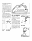
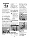
STEP 3: MOVE TILLER OFF CRATE
Toroll the tiller off the shipping platform,
put the wheels in freewheel,as follows:
1. Placeasturdy block underthe transmis-
sion to raiseone wheel about 1" off the
ground.
2, Removethe hairpin cotter (L, Fig.2-3)
and wheeldrive pin (M) from the wheel
hub (0) and wheelshaft (N).
3. Slidethe wheelfully inwardonthe wheel
shaft (N, Fig.2-3). Reinstallthe wheel